CLUTCH ACTUATOR(for EC65A) INSTALLATION
PROCEDURE
-
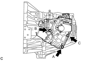
INSTALL CLUTCH ACTUATOR ASSEMBLY
-
Temporarily tighten the bolt A.
Note
Support the clutch actuator assembly until all 3 bolts are tightened.
-
Install the bolt B.
- Torque:
- 17 N*m { 173 kgf*cm, 13 ft.*lbf }
-
Install the bolt C.
- Torque:
- 17 N*m { 173 kgf*cm, 13 ft.*lbf }
-
Fully tighten the bolt A.
- Torque:
- 17 N*m { 173 kgf*cm, 13 ft.*lbf }
-
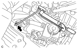
Using a 10 mm union nut wrench, install the bleeder clutch release tube.
- Torque:
- 15.2 N*m { 155 kgf*cm, 11 ft.*lbf }
Note
-
Use a torque wrench with a fulcrum length of 250 mm (9.84 in.).
-
Use the torque value compensation formula to calculate the torque value for use when a torque wrench is combined with a tool such as a union nut wrench.
-
Connect the wire harness with the bolt.
- Torque:
- 8.0 N*m { 82 kgf*cm, 71 in.*lbf }
-
Connect the clutch motor assembly connector.
-
Connect the clutch stroke sensor connector.
-
-
INSTALL NO. 2 BATTERY CARRIER
-
INSTALL BATTERY
-
INSTALL AIR CLEANER CASE SUB-ASSEMBLY
-
INSTALL AIR CLEANER CAP SUB-ASSEMBLY
-
INSTALL NO. 1 ENGINE COVER (w/ No. 1 Engine Cover)
-
INSTALL NO. 1 ENGINE UNDER COVER (for Half Cover Type)
-
INSTALL NO. 1 ENGINE UNDER COVER (for Full Cover Type)
-
BLEED CLUTCH LINE
-
PERFORM INITIALIZATION OF MULTI-MODE MANUAL TRANSMISSION SYSTEM
-
PERFORM LEARNING OF MULTI-MODE MANUAL TRANSMISSION SYSTEM
-
INSPECT FOR FLUID LEAK
Tech Tips
Check for leaks in the clutch system.