STOP AND START SYSTEM, Diagnostic DTC:P2531
| DTC Code | DTC Name |
|---|---|
| P2531 | Ignition Switch Run Position Circuit Low |
DESCRIPTION
If the engine stop and start ECU receives the OFF signal from the ignition or starter switch assembly*1 or certification ECU (smart key ECU assembly)*2 when communication with the ECM is normal, the engine stop and start ECU will store DTC P2531.
-
*1: w/o Entry and Start System
-
*2: w/ Entry and Start System
| DTC No. | Detection Item | DTC Detection Condition | Trouble Area | Warning Indicate | Memory |
|---|---|---|---|---|---|
| P2531 | Ignition Switch Run Position Circuit Low | Both of the following conditions are met for 10 seconds or more (1 trip detection logic):
|
|
Does not come on | DTC stored |
CONFIRMATION DRIVING PATTERN
Tech Tips
DTCs for the stop and start system are not cleared automatically even if the malfunction has been repaired. After repairing the malfunction, be sure to clear the DTCs.
-
Tech Tips
-
If the cable is disconnected from the negative (-) battery terminal, stop and start control is prohibited until refresh charge is completed. In this case, drive the vehicle approximately 5 to 40 minutes until refresh charge is completed and stop and start control operation is permitted.
-
Allow the engine to idle for 3 minutes after it is warmed up and check that the engine idle speed is within 50 rpm of the target idle speed.
CONFIRMATION AFTER TROUBLESHOOTING
-
Connect the GTS to the DLC3.
-
Turn the ignition switch to ON and turn the GTS on.
-
Clear the DTCs.
Powertrain > Stop and Start > Clear DTCs -
Start the engine and warm it up.
-
Drive the vehicle at 7 km/h (4.3 mph) or more.
CAUTION:
When performing Confirmation Driving Pattern, obey all speed limits and traffic laws.
-
Stop the vehicle, move the shift lever to neutral and release the clutch pedal. (for Manual Transaxle)
-
Depress the brake pedal and stop the vehicle. (for CVT)
-
Keep the engine stopped by stop and start control for 1 second or more. (Keep the shift lever in D. (for CVT))
-
Depress the clutch pedal and start the engine. (for Manual Transaxle)
Tech Tips
If the engine cranks slowly when the engine is restarted, it can be determined that the battery voltage is low.
-
Release the brake pedal with the shift lever in D to start the engine. (for CVT)
Tech Tips
If the engine cranks slowly when the engine is restarted, it can be determined that the battery voltage is low.
-
Check that DTCs are not output.
Powertrain > Stop and Start > Trouble Codes
-
-
STOP AND START SYSTEM OPERATION CHECK
Tech Tips
If the cable is disconnected from the negative (-) battery terminal, stop and start control is prohibited until refresh charge is completed. In this case, drive the vehicle approximately 5 to 40 minutes until refresh charge is completed and stop and start control operation is permitted.
-
Start the engine and warm it up.
-
Turn the air conditioning system off.
-
Drive the vehicle at 7 km/h (4.3 mph) or more.
CAUTION:
When performing Confirmation Driving Pattern, obey all speed limits and traffic laws.
-
Stop the vehicle, move the shift lever to neutral and release the clutch pedal. (for Manual Transaxle)
-
Depress the brake pedal and stop the vehicle. (for CVT)
-
Allow the engine to stop by stop and start control. (Keep the shift lever in D. (for CVT))
-
Depress the clutch pedal and start the engine. (for Manual Transaxle)
-
Release the brake pedal with the shift lever in D to start the engine. (for CVT)
-
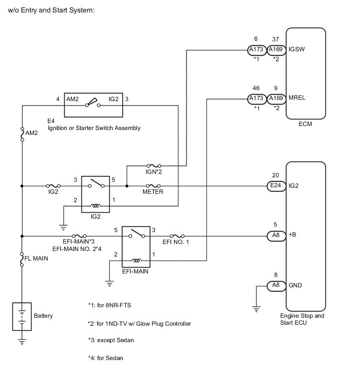
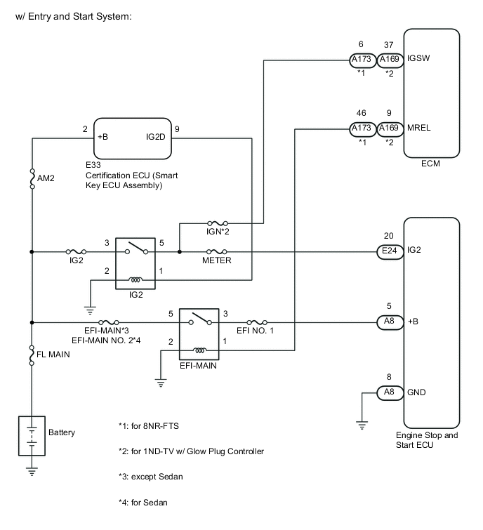
WIRING DIAGRAM
-
for 1WW
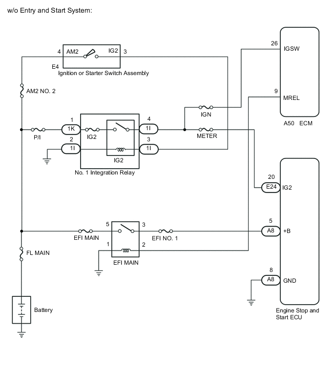
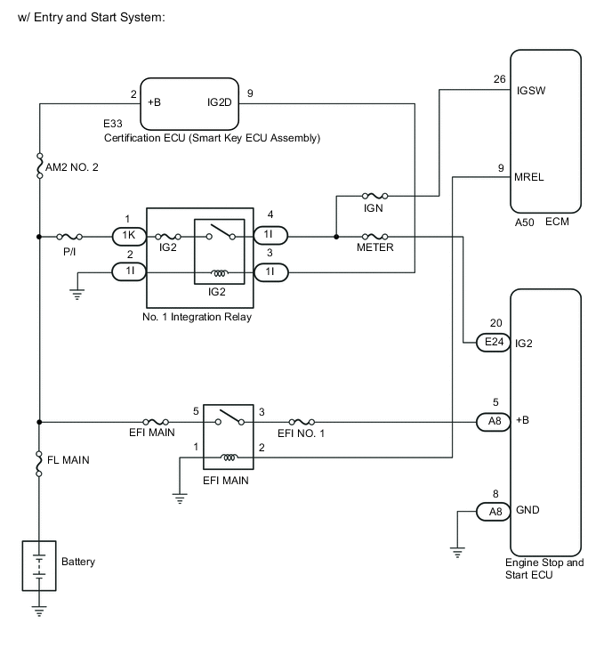
-
except 1WW
CAUTION / NOTICE / HINT
Note
-
Before replacing the engine stop and start ECU, read the number of starter operations and write it into a new engine stop and start ECU.
-
After replacing the engine stop and start ECU or air conditioning amplifier assembly, reset and perform learning of the air conditioning information in the engine stop and start ECU.
-
After replacing the engine stop and start ECU or airbag sensor assembly, clear and calibrate the deceleration sensor zero point in the engine stop and start ECU.
-
Inspect the fuses for circuits related to this system before performing the following procedure.
Tech Tips
Using the GTS, read the freeze frame data before troubleshooting. System condition information is recorded as freeze frame data the moment a DTC is stored. This information can be useful when troubleshooting.
PROCEDURE
-
READ VALUE USING GTS (IG SWITCH)
-
Connect the GTS to the DLC3.
-
Turn the ignition switch to ON.
-
Turn the GTS on.
-
Enter the following menus: Powertrain / Stop and Start / Data List / IG Switch.
Powertrain > Stop and Start > Data ListTester Display IG Switch -
Read the value displayed on the GTS.
Result Tester Display Result Proceed to IG Switch ON A OFF (for 1WW) B OFF (except 1WW) C
A 
USE SIMULATION METHOD TO CHECK Click here
C 
CHECK HARNESS AND CONNECTOR (ENGINE STOP AND START ECU - IG2 RELAY) Click here
B 
-
-
CHECK HARNESS AND CONNECTOR (ENGINE STOP AND START ECU - NO. 1 INTEGRATION RELAY (IG2 RELAY))
-
Disconnect the A50 ECM connector.
-
Disconnect the E24 engine stop and start ECU connector.
-
Disconnect the 1I No. 1 integration relay connector.
-
Measure the resistance according to the value(s) in the table below.
Standard Resistance Tester Connection Condition Specified Condition E24-20 (IG2) - 1I-4 Always Below 1 Ω E24-20 (IG2) - Body ground Always 10 kΩ or higher 1I-4 - Body ground Always 10 kΩ or higher Result Proceed to OK NG
NG
REPAIR OR REPLACE HARNESS OR CONNECTOR
OK
-
-
INSPECT NO. 1 INTEGRATION RELAY (IG2 RELAY)
-
Inspect the No. 1 integration relay (IG2 relay).
Result Proceed to OK NG
NG
REPLACE NO. 1 INTEGRATION RELAY (IG2 RELAY) Click here
OK
-
-
CHECK HARNESS AND CONNECTOR (NO. 1 INTEGRATION RELAY (IG2 RELAY) - BODY GROUND)
-
Disconnect the 1I No. 1 integration relay connector.
-
Measure the resistance according to the value(s) in the table below.
Standard Resistance Tester Connection Condition Specified Condition 1I-2 - Body ground Always Below 1 Ω Result Proceed to OK NG
NG
REPAIR OR REPLACE HARNESS OR CONNECTOR
OK
-
-
CHECK HARNESS AND CONNECTOR (NO. 1 INTEGRATION RELAY (IG2 RELAY) - IGNITION OR STARTER SWITCH ASSEMBLY OR CERTIFICATION ECU (SMART KEY ECU ASSEMBLY))
-
Disconnect the 1I No. 1 integration relay connector.
-
Disconnect the E4 ignition or starter switch assembly connector (w/o Entry and Start System).
-
Disconnect the E33 certification ECU (smart key ECU assembly) connector (w/ Entry and Start System).
-
Measure the resistance according to the value(s) in the table below.
Standard Resistance w/o Entry and Start System Tester Connection Condition Specified Condition 1I-3 - E4-3 (IG2) Always Below 1 Ω 1I-3 - Body ground Always 10 kΩ or higher E4-3 (IG2) - Body ground Always 10 kΩ or higher w/ Entry and Start System Tester Connection Condition Specified Condition 1I-3 - E33-9 (IG2D) Always Below 1 Ω 1I-3 - Body ground Always 10 kΩ or higher E33-9 (IG2D) - Body ground Always 10 kΩ or higher Result Proceed to OK NG
NG
REPAIR OR REPLACE HARNESS OR CONNECTOR
OK
-
-
CHECK HARNESS AND CONNECTOR (ENGINE STOP AND START ECU - EFI MAIN RELAY)
-
Disconnect the A8 engine stop and start ECU connector.
-
Remove the EFI MAIN relay from engine room relay block and junction block assembly.
-
Measure the resistance according to the value(s) in the table below.
Standard Resistance Tester Connection Condition Specified Condition A8-5 (+B) - EFI MAIN relay terminal 3 Always Below 1 Ω A8-5 (+B) - Body ground Always 10 kΩ or higher EFI MAIN relay terminal 3 - Body ground Always 10 kΩ or higher Result Proceed to OK NG
NG
REPAIR OR REPLACE HARNESS OR CONNECTOR
OK
-
-
CHECK ECM (IGSW TERMINAL VOLTAGE)
-
Disconnect the A50 ECM connector.
-
Turn the ignition switch to ON.
-
Measure the voltage according to the value(s) in the table below.
Standard Voltage Tester Connection Condition Specified Condition A50-26 (IGSW) - Body ground Ignition switch ON 9.5 to 14 V Result Proceed to OK NG
NG
GO TO ECM POWER SOURCE CIRCUIT Click here
OK
-
-
INSPECT RELAY (EFI MAIN RELAY)
-
Inspect the EFI MAIN relay.
Result Proceed to OK NG
NG
REPLACE RELAY (EFI MAIN RELAY)
OK
-
-
CHECK HARNESS AND CONNECTOR (EFI MAIN RELAY - ECM)
Tech Tips
If communication between the GTS and vehicle is possible and SFI system data can be read 30 seconds after turning the ignition switch off a malfunction in the EFI MAIN relay circuit is suspected.
-
Remove the EFI MAIN relay from engine room relay block and junction block assembly.
-
Disconnect the A50 ECM connector.
-
Measure the resistance according to the value(s) in the table below.
Standard Resistance Tester Connection Condition Specified Condition EFI MAIN relay terminal 2 - A50-9 (MREL) Always Below 1 Ω EFI MAIN relay terminal 2 - Body ground Always 10 kΩ or higher A50-9 (MREL) - Body ground Always 10 kΩ or higher Result Result Proceed to OK (w/o Entry and Start System) A OK (w/ Entry and Start System) B NG C
A
GO TO STEP 18 Click here
B
GO TO STEP 19 Click here
C
REPAIR OR REPLACE HARNESS OR CONNECTOR
-
-
CHECK HARNESS AND CONNECTOR (ENGINE STOP AND START ECU - IG2 RELAY)
-
Disconnect the A173*1 or A169*2 ECM connector.
-
*1: for 8NR-FTS
-
*2: for 1ND-TV w/ Glow Plug Controller
-
-
Disconnect the E24 engine stop and start ECU connector.
-
Remove the IG2 relay from engine room relay block and junction block assembly.
-
Measure the resistance according to the value(s) in the table below.
Standard Resistance Tester Connection Condition Specified Condition E24-20 (IG2) - IG2 relay terminal 5 Always Below 1 Ω E24-20 (IG2) - Body ground Always 10 kΩ or higher IG2 relay terminal 5 - Body ground Always 10 kΩ or higher Result Proceed to OK NG
NG
REPAIR OR REPLACE HARNESS OR CONNECTOR
OK
-
-
INSPECT RELAY (IG2 RELAY)
-
Inspect the IG2 relay.
for 1ND-TV: Click here
for 8NR-FTS: Click here
Result Proceed to OK NG
NG
REPLACE RELAY (IG2 RELAY)
OK
-
-
CHECK HARNESS AND CONNECTOR (IG2 RELAY - BODY GROUND)
-
Remove the IG2 relay from engine room relay block and junction block assembly.
-
Measure the resistance according to the value(s) in the table below.
Standard Resistance Tester Connection Condition Specified Condition IG2 relay terminal 2 - Body ground Always Below 1 Ω Result Proceed to OK NG
NG
REPAIR OR REPLACE HARNESS OR CONNECTOR
OK
-
-
CHECK HARNESS AND CONNECTOR (IG2 RELAY - IGNITION OR STARTER SWITCH ASSEMBLY OR CERTIFICATION ECU (SMART KEY ECU ASSEMBLY))
-
Remove the IG2 relay from engine room relay block and junction block assembly.
-
Disconnect the E4 ignition or starter switch assembly connector (w/o Entry and Start System).
-
Disconnect the E33 certification ECU (smart key ECU assembly) connector (w/ Entry and Start System).
-
Measure the resistance according to the value(s) in the table below.
Standard Resistance w/o Entry and Start System Tester Connection Condition Specified Condition IG2 relay terminal 1 - E4-3 (IG2) Always Below 1 Ω IG2 relay terminal 1 - Body ground Always 10 kΩ or higher E4-3 (IG2) - Body ground Always 10 kΩ or higher w/ Entry and Start System Tester Connection Condition Specified Condition IG2 relay terminal 1 - E33-9 (IG2D) Always Below 1 Ω IG2 relay terminal 1 - Body ground Always 10 kΩ or higher E33-9 (IG2D) - Body ground Always 10 kΩ or higher Result Proceed to OK NG
NG
REPAIR OR REPLACE HARNESS OR CONNECTOR
OK
-
-
CHECK HARNESS AND CONNECTOR (ENGINE STOP AND START ECU - EFI-MAIN RELAY)
-
Disconnect the A8 engine stop and start ECU connector.
-
Remove the EFI-MAIN relay from engine room relay block and junction block assembly.
-
Measure the resistance according to the value(s) in the table below.
Standard Resistance Tester Connection Condition Specified Condition A8-5 (+B) - EFI-MAIN relay terminal 3 Always Below 1 Ω A8-5 (+B) - Body ground Always 10 kΩ or higher EFI-MAIN relay terminal 3 - Body ground Always 10 kΩ or higher Result Proceed to OK NG
NG
REPAIR OR REPLACE HARNESS OR CONNECTOR
OK
-
-
CHECK ECM (IGSW TERMINAL VOLTAGE)
-
Disconnect the A173*1 or A169*2 ECM connector.
-
*1: for 8NR-FTS
-
*2: for 1ND-TV w/ Glow Plug Controller
-
-
Turn the ignition switch to ON.
-
Measure the voltage according to the value(s) in the table below.
Standard Voltage for 8NR-FTS Tester Connection Condition Specified Condition A173-6 (IGSW) - Body ground Ignition switch ON 9.5 to 14 V for 1ND-TV w/ Glow Plug Controller Tester Connection Condition Specified Condition A169-37 (IGSW) - Body ground Ignition switch ON 9.5 to 14 V Result Proceed to OK NG
NG
GO TO ECM POWER SOURCE CIRCUIT for 1ND-TV w/ Glow Plug Controller: Click here
GO TO ECM POWER SOURCE CIRCUIT for 1WW: Click here
GO TO ECM POWER SOURCE CIRCUIT for 8NR-FTS: Click hereOK
-
-
INSPECT RELAY (EFI-MAIN RELAY)
-
Inspect the EFI-MAIN relay.
for 1ND-TV: Click here
for 8NR-FTS: Click here
Result Proceed to OK NG
NG
REPLACE RELAY (EFI-MAIN RELAY)
OK
-
-
CHECK HARNESS AND CONNECTOR (EFI-MAIN RELAY - ECM)
Tech Tips
If communication between the GTS and vehicle is possible and SFI system data can be read 30 seconds after turning the ignition switch off a malfunction in the EFI-MAIN relay circuit is suspected.
-
Remove the EFI-MAIN relay from engine room relay block and junction block assembly.
-
Disconnect the A173*1 or A169*2 ECM connector.
-
*1: for 8NR-FTS
-
*2: for 1ND-TV w/ Glow Plug Controller
-
-
Measure the resistance according to the value(s) in the table below.
Standard Resistance for 8NR-FTS Tester Connection Condition Specified Condition EFI-MAIN relay terminal 1 - A173-46 (MREL) Always Below 1 Ω EFI-MAIN relay terminal 1 - Body ground Always 10 kΩ or higher A173-46 (MREL) - Body ground Always 10 kΩ or higher for 1ND-TV w/ Glow Plug Controller Tester Connection Condition Specified Condition EFI-MAIN relay terminal 1 - A169-9 (MREL) Always Below 1 Ω EFI-MAIN relay terminal 1 - Body ground Always 10 kΩ or higher A169-9 (MREL) - Body ground Always 10 kΩ or higher Result Result Proceed to OK (w/o Entry and Start System) A OK (w/ Entry and Start System) B NG C
B
CHECK CERTIFICATION ECU (SMART KEY ECU ASSEMBLY) (IG2D TERMINAL VOLTAGE) Click here
C
REPAIR OR REPLACE HARNESS OR CONNECTOR
A
-
-
INSPECT IGNITION OR STARTER SWITCH ASSEMBLY
-
Inspect the ignition or starter switch assembly.
for 1ND-TV: Click here
for 1WW: Click here
for 8NR-FTS: Click here
Result Proceed to OK NG
OK
REPLACE ENGINE STOP AND START ECU Click here
NG
REPLACE IGNITION OR STARTER SWITCH ASSEMBLY for 1ND-TV: Click here
REPLACE IGNITION OR STARTER SWITCH ASSEMBLY for 1WW: Click here
REPLACE IGNITION OR STARTER SWITCH ASSEMBLY for 8NR-FTS: Click here -
-
CHECK CERTIFICATION ECU (SMART KEY ECU ASSEMBLY) (IG2D TERMINAL VOLTAGE)
-
Measure the voltage according to the value(s) in the table below.
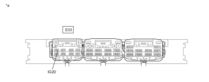
*a Component with harness connected
(Certification ECU (Smart Key ECU Assembly))
- - Standard Voltage Tester Connection Condition Specified Condition E33-9 (IG2D) - Body ground Ignition switch ACC 1 V or less E33-9 (IG2D) - Body ground Ignition switch ON 9 V or higher Result Proceed to OK NG
OK
REPLACE ENGINE STOP AND START ECU Click here
NG
REPLACE CERTIFICATION ECU (SMART KEY ECU ASSEMBLY)
-