STOP AND START SYSTEM, Diagnostic DTC:P1862
| DTC Code | DTC Name |
|---|---|
| P1862 | Clutch Control System 2 |
DESCRIPTION
There are 2 clutch pedal switches for the clutch pedal. The clutch start switch assembly (for upper) is used for stopping and restarting of the engine by stop and start control. During the stop and start control, the clutch start switch assembly (for lower) is used only when the clutch start switch assembly (for upper) is stuck on or the fail-safe function is activated.
| DTC No. | Detection Item | DTC Detection Condition | Trouble Area | Warning Indicate | Memory |
|---|---|---|---|---|---|
| P1862 | Clutch Control System 2 | Both of the following conditions continue for 0.5 seconds or more (1 trip detection logic):
|
|
Blinking | DTC stored |
CONFIRMATION DRIVING PATTERN
Tech Tips
DTCs for the stop and start system are not cleared even automatically if the malfunction has been repaired. After repairing the malfunction, be sure to clear the DTCs.
-
CONFIRMATION AFTER TROUBLESHOOTING
Tech Tips
-
If the cable is disconnected from the negative (-) battery terminal, stop and start control is prohibited until refresh charge is completed. In this case, drive the vehicle approximately 5 to 40 minutes until refresh charge is completed and stop and start control operation is permitted.
-
Allow the engine to idle for 3 minutes after it is warmed up and check that the engine idle speed is within 50 rpm of the target idle speed.
-
Connect the GTS to the DLC3.
-
Turn the ignition switch to ON and turn the GTS on.
-
Clear the DTCs.
Powertrain > Stop and Start > Clear DTCs -
Start the engine.
-
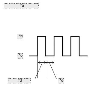
*a Clutch Switch Signal *b ON *c OFF *d 1 second or more Fully depress the clutch pedal for 1 second or more. Release the clutch pedal and wait for at least 1 second.
-
Repeat the previous step 3 times.
-
Check that no DTCs are output.
Powertrain > Stop and Start > Trouble Codes
-
-
STOP AND START SYSTEM OPERATION CHECK
Tech Tips
If the cable is disconnected from the negative (-) battery terminal, stop and start control is prohibited until refresh charge is completed. In this case, drive the vehicle approximately 5 to 40 minutes until refresh charge is completed and stop and start control operation is permitted.
-
Start the engine and warm it up.
-
Turn the air conditioning system off.
-
Drive the vehicle at 7 km/h (4.3 mph) or more.
CAUTION:
When performing Confirmation Driving Pattern, obey all speed limits and traffic laws.
-
Stop the vehicle, move the shift lever to neutral and release the clutch pedal.
-
Allow the engine to stop by stop and start control
-
Depress the clutch pedal and start the engine.
-
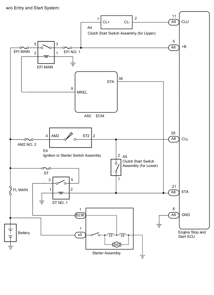
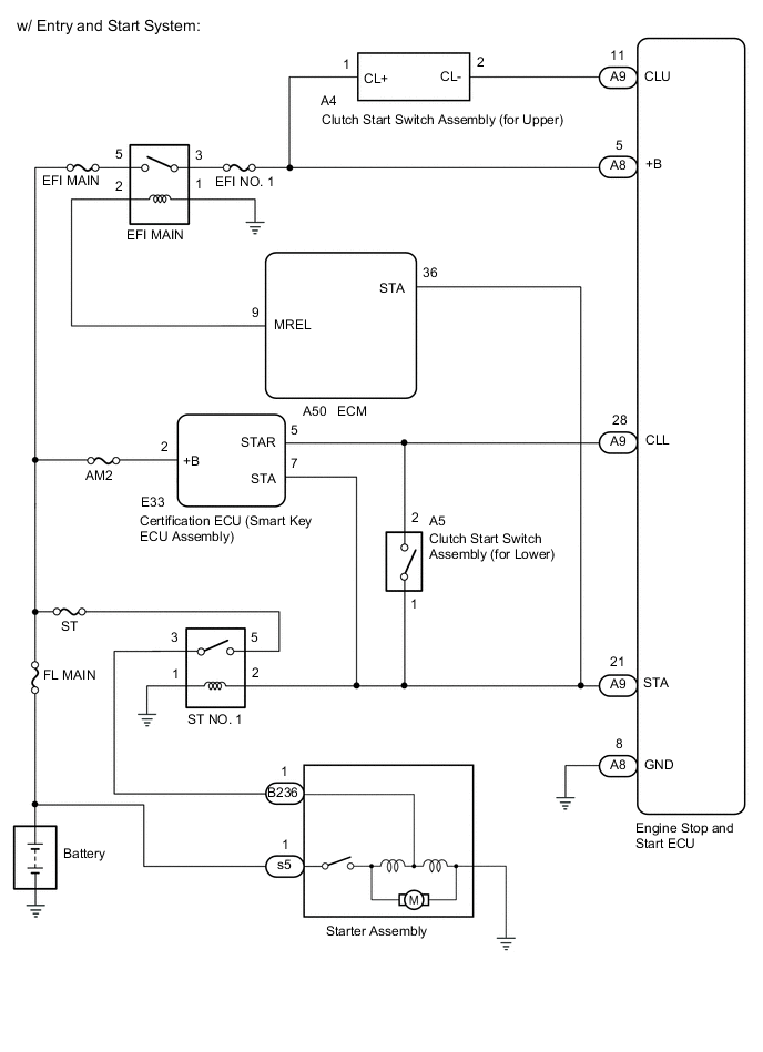
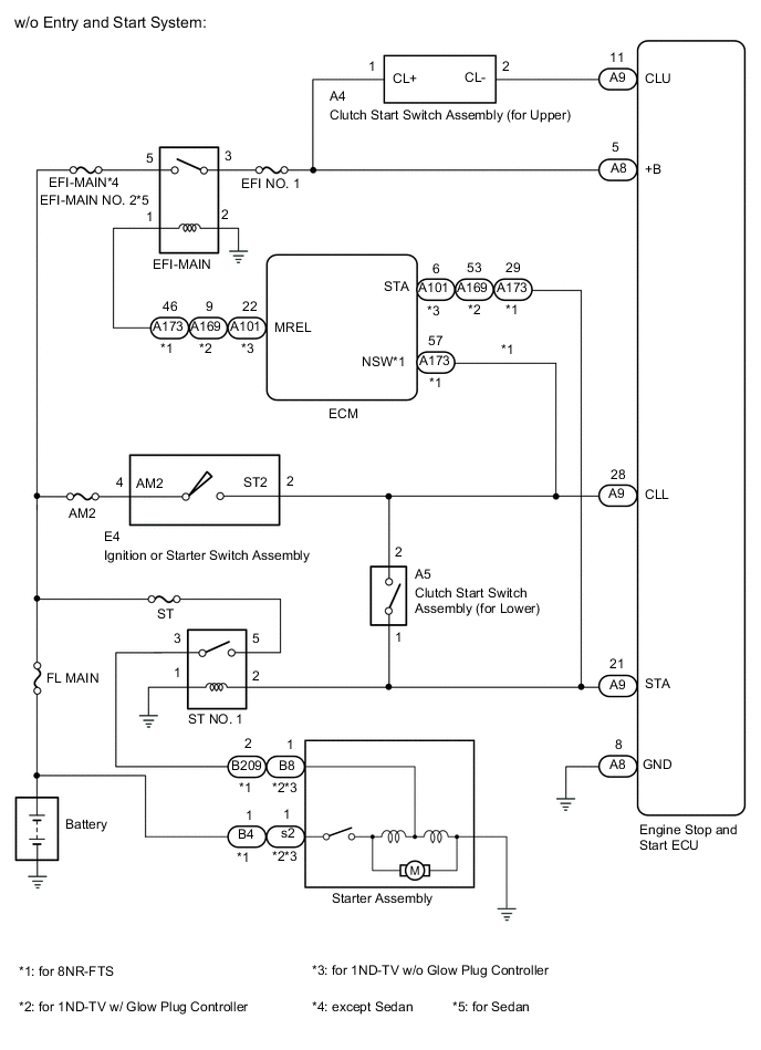
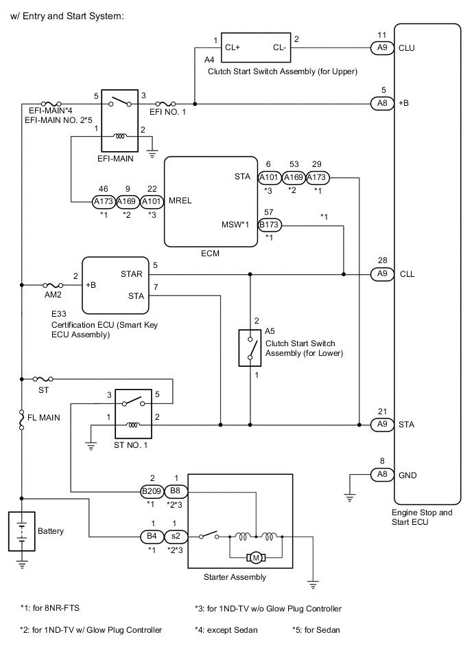
WIRING DIAGRAM
-
for 1WW
-
except 1WW
CAUTION / NOTICE / HINT
Note
-
Before replacing the engine stop and start ECU, read the number of starter operations and write it into a new engine stop and start ECU.
-
After replacing the engine stop and start ECU or air conditioning amplifier assembly, reset and perform learning of the air conditioning information in the engine stop and start ECU.
-
After replacing the engine stop and start ECU or airbag sensor assembly, clear and calibrate the deceleration sensor zero point in the engine stop and start ECU.
Tech Tips
Using the GTS, read the freeze frame data before troubleshooting. System condition information is recorded as freeze frame data the moment a DTC is stored. This information can be useful when troubleshooting.
PROCEDURE
-
READ VALUE USING GTS (CLUTCH UPPER SW AND CLUTCH LOWER SW)
-
Connect the GTS to the DLC3.
-
Turn the ignition switch to ON.
-
Turn the GTS on.
-
Enter the following menus: Powertrain / Stop and Start / Data List / Clutch Upper SW and Clutch Lower SW.
Powertrain > Stop and Start > Data ListTester Display Clutch Upper SW Clutch Lower SW -
Depress the clutch pedal and read the values displayed on the GTS.
OK Tester Display Condition Normal Condition Clutch Upper SW Fully Depressed OFF Clutch Lower SW Fully Depressed ON Clutch Upper SW Fully Released ON Clutch Lower SW Fully Released OFF Result Result Proceed to NG A OK B
B 
USE SIMULATION METHOD TO CHECK Click here
A 
-
-
INSPECT CLUTCH START SWITCH ASSEMBLY (FOR LOWER)
-
Inspect the clutch start switch assembly (for lower).
Result Proceed to OK NG
NG
REPLACE CLUTCH START SWITCH ASSEMBLY (FOR LOWER) Click here
OK
-
-
INSPECT CLUTCH START SWITCH ASSEMBLY (FOR UPPER)
-
Inspect the clutch start switch assembly (for upper).
Result Proceed to OK NG
NG
REPLACE CLUTCH START SWITCH ASSEMBLY (FOR UPPER) Click here
OK
-
-
CHECK HARNESS AND CONNECTOR (ENGINE STOP AND START ECU - CLUTCH START SWITCH ASSEMBLY (FOR LOWER))
-
Disconnect the A9 engine stop and start ECU connector.
-
Disconnect the A5 clutch start switch assembly (for lower) connector.
-
Disconnect the B173 ECM connector (for 8NR-FTS).
-
Disconnect the E33 certification ECU (smart key ECU assembly) connector (w/ Entry and Start System).
-
Disconnect the E4 ignition or starter switch assembly connector (w/o Entry and Start System).
-
Measure the resistance according to the value(s) in the table below.
Standard Resistance Tester Connection Condition Specified Condition A9-28 (CLL) - A5-2 Always Below 1 Ω A9-28 (CLL) - Body ground Always 10 kΩ or higher A5-2 - Body ground Always 10 kΩ or higher Result Proceed to OK NG
NG
REPAIR OR REPLACE HARNESS OR CONNECTOR
OK
-
-
CHECK HARNESS AND CONNECTOR (ENGINE STOP AND START ECU - CLUTCH START SWITCH ASSEMBLY (FOR UPPER))
-
Disconnect the A9 engine stop and start ECU connector.
-
Disconnect the A4 clutch start switch assembly (for upper) connector.
-
Measure the resistance according to the value(s) in the table below.
Standard Resistance Tester Connection Condition Specified Condition A9-11 (CLU) - A4-2 (CL-) Always Below 1 Ω A9-11 (CLU) - Body ground Always 10 kΩ or higher A4-2 (CL-) - Body ground Always 10 kΩ or higher Result Proceed to OK NG
OK
REPLACE ENGINE STOP AND START ECU Click here
NG
REPAIR OR REPLACE HARNESS OR CONNECTOR
-