STOP AND START SYSTEM, Diagnostic DTC:P1780
| DTC Code | DTC Name |
|---|---|
| P1780 | Discrepancy between Neutral Position SW and Shift Position |
DESCRIPTION
The engine stop and start ECU detects a malfunction by comparing the shift position signal with the neutral position switch signal input state. If a malfunction is detected, the engine stop and start ECU blinks the stop and start cancel indicator light, prohibits the stop and start control and stores DTC P1780. (for Manual Transaxle)
The engine stop and start ECU detects malfunctions by comparing the conditions of the shift position signal and NSW signal. If a malfunction is detected, the engine stop and start ECU blinks the stop and start cancel indicator light, prohibits stop and start control and stores DTC P1780. (for CVT)
| DTC No. | Detection Item | DTC Detection Condition | Trouble Area | Warning Indicate | Memory |
|---|---|---|---|---|---|
| P1780 | Discrepancy between Neutral Position SW and Shift Position | The following condition continues for 1 seconds or more (1 trip detection logic) (for Manual Transaxle):
Both of the following conditions are met for 2 seconds or more (2 trip detection logic) (for CVT) (*1):
Both of the following conditions are met for 2 seconds or more (2 trip detection logic) (for CVT) (*1):
Both of the following conditions are met for 15 seconds or more (2 trip detection logic) (for CVT) (*2):
|
|
Blinking | DTC stored |
*1: "ON" is displayed for the freeze frame data item [Neutral Switch Stuck ON]
*2: "ON" is displayed for the freeze frame data item [Neutral Switch Stuck OFF]
WIRING DIAGRAM
-
for Manual Transaxle
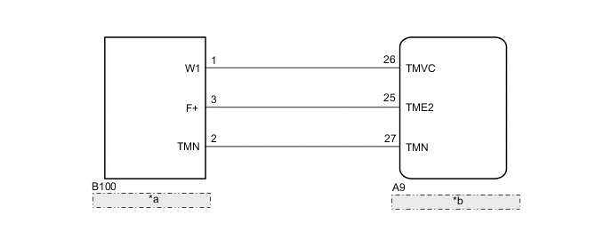
*a Neutral Position Switch *b Engine Stop and Start ECU -
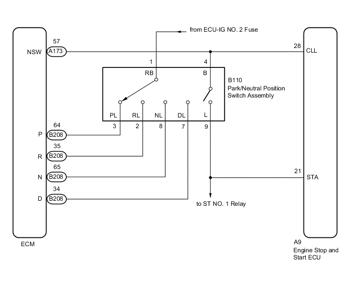
for CVT
CAUTION / NOTICE / HINT
Note
-
Before replacing the engine stop and start ECU, read the number of starter operations and write it into a new engine stop and start ECU.
-
After replacing the engine stop and start ECU or air conditioning amplifier assembly, reset and perform learning of the air conditioning information in the engine stop and start ECU.
-
After replacing the engine stop and start ECU or airbag sensor assembly, clear and calibrate the deceleration sensor zero point in the engine stop and start ECU.
Tech Tips
Using the GTS, read the freeze frame data before troubleshooting. System condition information is recorded as freeze frame data the moment a DTC is stored. This information can be useful when troubleshooting.
PROCEDURE
-
CONFIRM MODEL
-
Choose the model to be inspected.
Result Result Proceed to for Manual Transaxle A for CVT B
B 
READ VALUE USING GTS Click here
A 
-
-
READ VALUE USING GTS (NEUTRAL SWITCH)
-
Connect the GTS to the DLC3.
-
Turn the ignition switch to ON.
-
Turn the GTS on.
-
Enter the following menus: Powertrain / Stop and Start / Data List / Neutral Switch.
Powertrain > Stop and Start > Data ListTester Display Neutral Switch -
Read the value when the shift lever is in neutral and any other position
OK Tester Display Condition Normal Condition Neutral Switch Shift lever in neutral ON Shift lever in any position other than neutral OFF Result Proceed to OK NG
OK 
USE SIMULATION METHOD TO CHECK Click here
NG
-
-
CHECK HARNESS AND CONNECTOR (ENGINE STOP AND START ECU - NEUTRAL POSITION SWITCH)
-
Disconnect the A9 engine stop and start ECU connector.
-
Disconnect the B100 neutral position switch connector.
-
Measure the resistance according to the value(s) in the table below.
Standard Resistance Tester Connection Condition Specified Condition A9-26 (TMVC) - B100-1 (W1) Always Below 1 Ω A9-25 (TME2) - B100-3 (F+) Always Below 1 Ω A9-27 (TMN) - B100-2 (TMN) Always Below 1 Ω A9-26 (TMVC) - Body ground Always 10 kΩ or higher B100-1 (W1) - Body ground Always 10 kΩ or higher A9-25 (TME2) - Body ground Always 10 kΩ or higher B100-3 (F+) - Body ground Always 10 kΩ or higher A9-27 (TMN) - Body ground Always 10 kΩ or higher B100-2 (TMN) - Body ground Always 10 kΩ or higher Result Proceed to OK NG
NG
REPAIR OR REPLACE HARNESS OR CONNECTOR
OK
-
-
CHECK ENGINE STOP AND START ECU (TMN TERMINAL VOLTAGE)
-
Measure the voltage according to the value(s) in the table below.
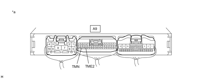
*a Component with harness connected
(Engine Stop and Start ECU)
- - Standard Voltage Tester Connection Condition Specified Condition A9-27 (TMN) - A9-25 (TME2) Ignition switch ON, shift lever in neutral 2.7 to 4.3 V Ignition switch ON, shift lever in any position other than neutral 0.7 to 1.9 V Result Proceed to OK NG
OK
REPLACE ENGINE STOP AND START ECU Click here
NG
REPLACE NEUTRAL POSITION SWITCH for 1WW: Click here
REPLACE NEUTRAL POSITION SWITCH for 1ND-TV: Click here
REPLACE NEUTRAL POSITION SWITCH for 8NR-FTS: Click here -
-
READ VALUE USING GTS
-
Connect the GTS to the DLC3.
-
Turn the ignition switch to ON.
-
Turn the GTS on.
-
Enter the following menus: Powertrain / Engine and ECT / Data List.
-
In accordance with the display on the GTS, read the Data List.
Powertrain > ECT > Data ListTester Display Measurement Item Range Normal Condition Diagnostic Note Shift SW Status (P Range) Park/neutral position switch assembly status OFF or ON OFF: Shift lever not in P
ON: Shift lever in P
- Shift SW Status (R Range) Park/neutral position switch assembly status OFF or ON OFF: Shift lever not in R
ON: Shift lever in R
- Shift SW Status (N Range) Park/neutral position switch assembly status OFF or ON OFF: Shift lever not in N
ON: Shift lever in N
- Shift SW Status (D Range) Park/neutral position switch assembly status OFF or ON OFF: Shift lever not in D or M
ON: Shift lever in D or M
-
Powertrain > ECT > Data ListTester Display Shift SW Status (P Range) Shift SW Status (R Range) Shift SW Status (N Range) Shift SW Status (D Range) Result Proceed to OK NG
NG
INSPECT PARK/NEUTRAL POSITION SWITCH ASSEMBLY Click here
OK
-
-
READ VALUE USING GTS (NEUTRAL POSITION SW OR NEUTRAL POSITION SW SIGNAL)
-
Enter the following menus: Powertrain / Engine and ECT / Data List.
-
In accordance with the display on the GTS, read the Data List.
Powertrain > ECT > Data ListTester Display Measurement Item Range Normal Condition Diagnostic Note Neutral Position SW Signal Park/neutral position switch assembly status OFF or ON OFF: Shift lever not in P or N
ON: Shift lever in P or N
-
Powertrain > ECT > Data ListTester Display Neutral Position SW Signal Result Proceed to OK NG
OK
USE SIMULATION METHOD TO CHECK Click here
NG
-
-
INSPECT PARK/NEUTRAL POSITION SWITCH ASSEMBLY
-
Inspect the park/neutral position switch assembly.
Result Proceed to OK NG
NG
REPLACE PARK/NEUTRAL POSITION SWITCH ASSEMBLY Click here
OK
-
-
CHECK HARNESS AND CONNECTOR (ENGINE STOP AND START ECU - PARK/NEUTRAL POSITION SWITCH ASSEMBLY)
-
Disconnect the A9 engine stop and start ECU connector.
-
Disconnect the B110 park/neutral position switch assembly connector.
-
Measure the resistance according to the value(s) in the table below.
Standard Resistance Tester Connection Condition Specified Condition A9-21 (STA) - B110-9 (L) Always Below 1 Ω A9-28 (CLL) - B110-4 (B) Always Below 1 Ω A9-21 (STA) - Body ground Always 80 to 180 Ω A9-28 (CLL) - Body ground Always 10 kΩ or higher B110-9 (L) - Body ground Always 80 to 180 Ω B110-4 (B) - Body ground Always 10 kΩ or higher Result Proceed to OK NG
OK
REPLACE ENGINE STOP AND START ECU Click here
NG
REPAIR OR REPLACE HARNESS OR CONNECTOR
-
-
INSPECT PARK/NEUTRAL POSITION SWITCH ASSEMBLY
-
Inspect the park/neutral position switch assembly.
Result Proceed to OK NG
NG
REPLACE PARK/NEUTRAL POSITION SWITCH ASSEMBLY Click here
OK
-
-
CHECK HARNESS AND CONNECTOR (ECM - PARK/NEUTRAL POSITION SWITCH ASSEMBLY)
-
Disconnect the A173 and B208 ECM connectors.
-
Disconnect the B110 park/neutral position switch assembly connector.
-
Measure the resistance according to the value(s) in the table below.
Standard Resistance Tester Connection Condition Specified Condition B208-64 (P) - B110-3 (PL) Always Below 1 Ω B208-35 (R) - B110-2 (RL) Always Below 1 Ω B208-65 (N) - B110-8 (NL) Always Below 1 Ω B208-34 (D) - B110-7 (DL) Always Below 1 Ω A173-57 (NSW) - B110-4 (B) Always Below 1 Ω Result Proceed to OK NG
OK
REPLACE ECM Click here
NG
REPAIR OR REPLACE HARNESS OR CONNECTOR
-