SPEED LIMITER SYSTEM TERMINALS OF ECM
-
CHECK ECM
Figure 1. for 1NR-FE and 1ZR-FAE
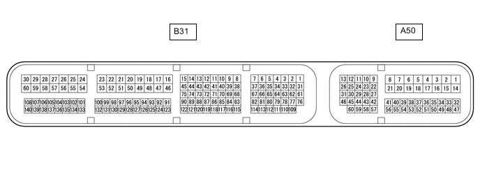
Terminal No. (Symbol) Wiring Color Terminal Description Condition Specified Condition A50-1 (BATT) - Body ground P - Body ground Power source circuit Always 11 to 14 V A50-37 (IGSW) - Body ground B - Body ground IG power source circuit Ignition switch ON 11 to 14 V Ignition switch off Below 1 V A50-40 (ASLM) - Body ground GR - Body ground Speed limiter switch signal Speed limiter switch on Below 1 Ω Speed limiter switch off 10 kΩ or higher B31-16 (E1) - Body ground BR - Body ground Ground Always Below 1 Ω Figure 2. for 1AD-FTV
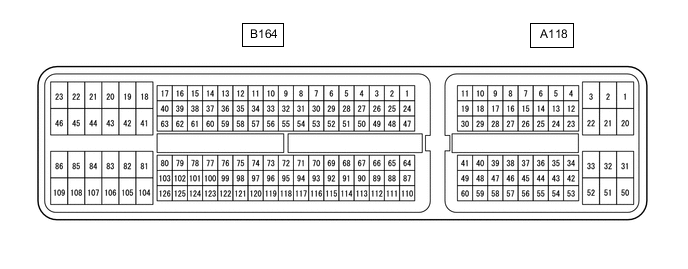
Terminal No. (Symbol) Wiring Color Terminal Description Condition Specified Condition A118-2 (BATT) - Body ground W - Body ground Power source circuit Always 11 to 14 V A118-25 (IGSW) - Body ground B - Body ground IG power source circuit Ignition switch ON 11 to 14 V Ignition switch off Below 1 V A118-24 (ASLM) - Body ground GR - Body ground Speed limiter switch signal Speed limiter switch on Below 1 Ω Speed limiter switch off 10 kΩ or higher B164-109 (E1) - Body ground BR - Body ground Ground Always Below 1 Ω