CRUISE CONTROL SYSTEM(except 1ND-TV, 8NR-FTS) Clutch Switch Circuit
DESCRIPTION
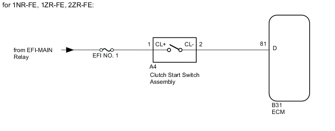
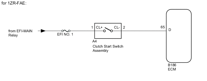
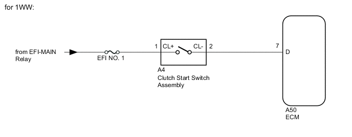
While depressing the clutch pedal, the clutch start switch sends a signal to terminal (D) of the ECM. The ECM cancels cruise control when terminal (D) receives the signal.
WIRING DIAGRAM
CAUTION / NOTICE / HINT
Note
Inspect the fuses for circuits related to this system before performing the following procedure.
PROCEDURE
-
INSPECT CLUTCH START SWITCH ASSEMBLY
-
Inspect the No. 2 clutch pedal switch assembly.
Result Proceed to OK NG
NG 
REPLACE CLUTCH START SWITCH ASSEMBLY Click here
OK 
-
-
CHECK HARNESS AND CONNECTOR (CLUTCH START SWITCH ASSEMBLY - BATTERY)
-
Disconnect the clutch start switch assembly connector.
-
Measure the voltage according to the value(s) in the table below.
Standard Voltage Tester Connection Condition Specified Condition A4-1 (CL+) - Body ground Ignition switch ON 11 to 14 V A4-1 (CL+) - Body ground Ignition switch off Below 1 V -
Reconnect the clutch start switch assembly connector.
Result Proceed to OK NG
NG
REPAIR OR REPLACE HARNESS OR CONNECTOR (CLUTCH START SWITCH ASSEMBLY - BATTERY)
OK
-
-
CHECK HARNESS AND CONNECTOR (ECM - CLUTCH START SWITCH ASSEMBLY)
-
Disconnect the clutch start switch assembly connector.
-
Disconnect the ECM connector.
-
Measure the resistance according to the value(s) in the table below.
Standard Resistance (Check for Open) for 1NR-FE, 1ZR-FE, 2ZR-FE Tester Connection Condition Specified Condition B31-81 (D) - A4-2 (CL-) Always Below 1 Ω for 1ZR-FAE Tester Connection Condition Specified Condition B186-65 (D) - A4-2 (CL-) Always Below 1 Ω for 1WW Tester Connection Condition Specified Condition A50-7 (D) - A4-2 (CL-) Always Below 1 Ω Standard Resistance (Check for Short) for 1NR-FE, 1ZR-FE, 2ZR-FE Tester Connection Condition Specified Condition B31-81 (D) or A4-2 (CL-) - Body ground Always 10 kΩ or higher for 1ZR-FAE Tester Connection Condition Specified Condition B186-65 (D) or A4-2 (CL-) - Body ground Always 10 kΩ or higher for 1WW Tester Connection Condition Specified Condition A50-7 (D) or A4-2 (CL-) - Body ground Always 10 kΩ or higher -
Reconnect the clutch start switch assembly connector.
-
Reconnect the ECM connector.
Result Proceed to OK NG
OK
PROCEED TO NEXT SUSPECTED AREA SHOWN IN PROBLEM SYMPTOMS TABLE Click here
NG
REPAIR OR REPLACE HARNESS OR CONNECTOR (CLUTCH START SWITCH ASSEMBLY - ECM)
-