CRUISE CONTROL SYSTEM(except 1ND-TV, 8NR-FTS) Cruise Control Switch Circuit
DESCRIPTION
The cruise control switch is used to turn the cruise control system on and off, as well as operate 7 functions: SET, - (COAST), TAP-DOWN, RES (RESUME), + (ACCEL), TAP-UP and CANCEL. The SET, TAP-DOWN and - (COAST) functions, and the RES (RESUME), TAP-UP and + (ACCEL) functions are operated with the same switch. The cruise control switch is an automatic return type switch which turns on only while operating it in the direction of each arrow and turns off after releasing it. The internal contact points of the cruise control switch turn on with switch operation. Then the ECM reads the voltage value that has been changed by the switch operation to control SET, - (COAST), RES (RESUME), + (ACCEL), and CANCEL.
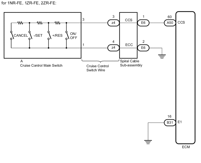
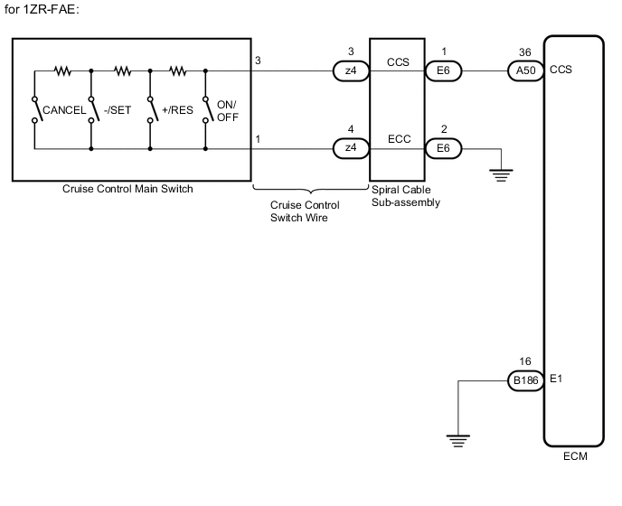
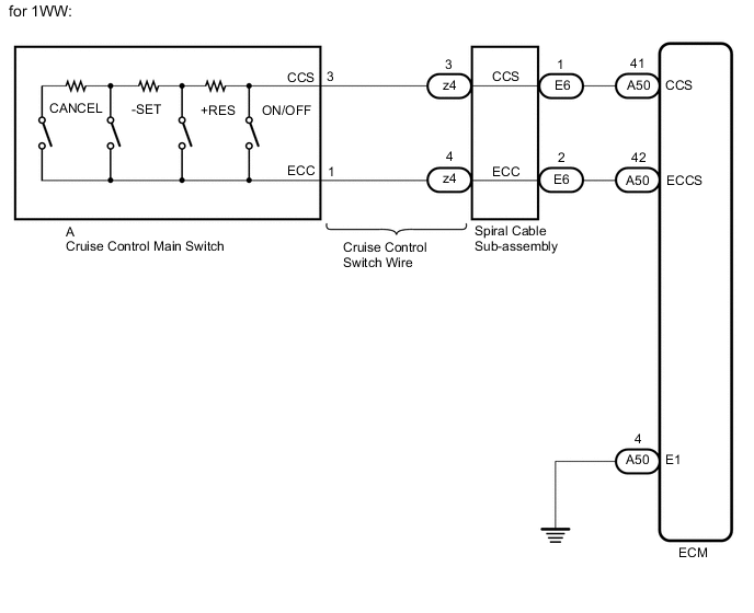
WIRING DIAGRAM
CAUTION / NOTICE / HINT
Note
Before replacing the ECM, refer to Service Bulletin.
PROCEDURE
-
READ VALUE ON GTS
-
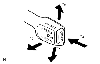
*a ON-OFF *b -/SET *c +/RES *d CANCEL Connect the GTS to the DLC3.
-
Turn the ignition switch to ON.
-
Turn the GTS on.
-
Enter the following menus: Powertrain / Cruise Control / Data List.
-
for 1NR-FE, 1ZR-FAE, 1ZR-FE, 2ZR-FE:
Check the Data List to confirm proper functioning of the cruise control switch.
Powertrain > Cruise Control > Data ListTester Display Measurement Item Range Normal Condition Diagnostic Note Main SW M-CPU Cruise control switch signal (Main CPU) ON or OFF ON: Cruise control switch (ON-OFF button) pushed
OFF: Cruise control switch (ON-OFF button) released
- Cancel Switch CANCEL switch signal ON or OFF ON: CANCEL switch on
OFF: CANCEL switch off
- SET/COAST Switch -/SET switch signal ON or OFF ON: -/SET switch on
OFF: -/SET switch off
- RES/ACC Switch +/RES switch signal ON or OFF ON: +/RES switch on
OFF: +/RES switch off
-
Powertrain > Cruise Control > Data ListTester Display Main SW M-CPU Cancel Switch SET/COAST Switch RES/ACC Switch -
for 1WW:
Check the Data List to confirm proper functioning of the cruise control switch.
Powertrain > Cruise Control > Data ListTester Display Measurement Item Range Normal Condition Diagnostic Note CANCEL SW CANCEL switch signal ON or OFF ON: CANCEL switch on
OFF: CANCEL switch off
- -SET SW -SET switch signal ON or OFF ON: -SET switch on
OFF: -SET switch off
- +RES SW +RES switch signal ON or OFF ON: +RES switch on
OFF: +RES switch off
- Cruise Control Switch Cruise control switch signal ON or OFF ON: Cruise control switch (ON-OFF switch) pushed
OFF: Cruise control switch (ON-OFF switch) released
-
Powertrain > Cruise Control > Data ListTester Display CANCEL SW -SET SW +RES SW Cruise Control Switch OK When the cruise control switch is operated, the display changes as shown above. Result Proceed to OK NG
OK 
PROCEED TO NEXT SUSPECTED AREA SHOWN IN PROBLEM SYMPTOMS TABLE Click here
NG 
-
-
INSPECT CRUISE CONTROL SWITCH
-
Remove the cruise control switch.
-
Measure the resistance according to the value(s) in the table below.
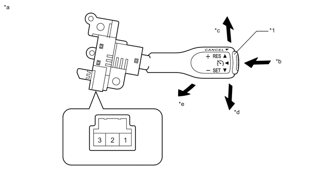
*1 Cruise Control Switch (ON-OFF button) - - *a Component without harness connected
(Cruise Control Switch (Cruise Control Main Switch))
*b ON-OFF *c +/RES *d -/SET *e CANCEL - - Standard Resistance Tester Connection Condition Specified Condition 1 - 3 Cruise control switch (ON-OFF button) released 1 MΩ or higher Cruise control switch (ON-OFF button) pushed Below 2.5 Ω +/RES switch ON 235 to 245 Ω -/SET switch ON 617 to 643 Ω CANCEL switch ON 1509 to 1571 Ω Result Proceed to OK NG
NG
REPLACE CRUISE CONTROL SWITCH Click here
OK
-
-
CHECK CRUISE CONTROL SWITCH WIRE
-
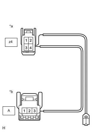
*a Front view of wire harness connector
(to Spiral Cable Sub-assembly)
*b Front view of wire harness connector
(to Cruise Control Main Switch)
Remove the cruise control switch wire.
-
Measure the resistance according to the value(s) in the table below.
Standard Resistance (Check for Open) Tester Connection Condition Specified Condition A-3 - z4-3 Always Below 1 Ω A-1 - z4-4 Always Below 1 Ω Result Proceed to OK NG
NG
REPLACE CRUISE CONTROL SWITCH WIRE
OK
-
-
INSPECT SPIRAL CABLE SUB-ASSEMBLY
-
Inspect the spiral cable sub-assembly.
w/ VSC: Click here
w/o VSC: Click here
Result Result Proceed to OK A NG (w/ VSC) B NG (w/o VSC) C
B
REPLACE SPIRAL CABLE WITH SENSOR SUB-ASSEMBLY Click here
C
REPLACE SPIRAL CABLE SUB-ASSEMBLY Click here
A
-
-
CHECK HARNESS AND CONNECTOR (SPIRAL CABLE SUB-ASSEMBLY - ECM AND BODY GROUND)
-
Disconnect the ECM connector.
-
Disconnect the spiral cable sub-assembly connector.
-
Measure the resistance according to the value(s) in the table below.
Standard Resistance (Check for Open) for 1NR-FE, 1ZR-FE, 2ZR-FE Tester Connection Condition Specified Condition A50-60 (CCS) - E6-1 (CCS) Always Below 1 Ω for 1ZR-FAE Tester Connection Condition Specified Condition A50-36 (CCS) - E6-1 (CCS) Always Below 1 Ω for 1WW Tester Connection Condition Specified Condition A50-41 (CCS) - E6-1 (CCS) Always Below 1 Ω A50-42 (ECCS) - E6-2 (ECC) Always Below 1 Ω Standard Resistance (Check for Short) for 1NR-FE, 1ZR-FE, 2ZR-FE Tester Connection Condition Specified Condition A50-60 (CCS) or E6-1 (CCS) - Body ground Always 10 kΩ or higher for 1ZR-FAE Tester Connection Condition Specified Condition A50-36 (CCS) or E6-1 (CCS) - Body ground Always 10 kΩ or higher for 1WW Tester Connection Condition Specified Condition A50-41 (CCS) or E6-1 (CCS) - Body ground Always 10 kΩ or higher A50-42 (ECCS) or E6-2 (ECC) - Body ground Always 10 kΩ or higher -
Reconnect the spiral cable sub-assembly connector.
-
Reconnect the ECM connector.
Result Result Proceed to OK (for 1NR-FE, 1ZR-FAE, 1ZR-FE, 2ZR-FE) A OK (for 1WW) B NG C
B 
CHECK HARNESS AND CONNECTOR (ECM - BODY GROUND) Click here
C
REPAIR OR REPLACE HARNESS OR CONNECTOR (SPIRAL CABLE SUB-ASSEMBLY - ECM)
A
-
-
CHECK HARNESS AND CONNECTOR (SPIRAL CABLE SUB-ASSEMBLY - BODY GROUND)
-
Disconnect the spiral cable sub-assembly connector.
-
Measure the resistance according to the value(s) in the table below.
Standard Resistance (Check for Open) Tester Connection Condition Specified Condition E6-2 (ECC) - Body ground Always Below 1 Ω Result Proceed to OK NG -
Reconnect the spiral cable sub-assembly connector.
OK
REPLACE ECM for 1NR-FE: Click here
REPLACE ECM for 1ZR-FAE: Click here
REPLACE ECM for 1ZR-FE: Click here
REPLACE ECM for 2ZR-FE: Click hereNG
REPAIR OR REPLACE HARNESS OR CONNECTOR (SPIRAL CABLE SUB-ASSEMBLY - BODY GROUND)
-
-
CHECK HARNESS AND CONNECTOR (ECM - BODY GROUND)
-
Disconnect the ECM connector.
-
Measure the resistance according to the value(s) in the table below.
Standard Resistance (Check for Open) Tester Connection Condition Specified Condition A50-4 (E1) - Body ground Always Below 1 Ω -
Reconnect the ECM connector.
Result Proceed to OK NG
OK
REPLACE ECM Click here
NG
REPAIR OR REPLACE HARNESS OR CONNECTOR (ECM - BODY GROUND)
-