CRUISE CONTROL SYSTEM(except 1ND-TV, 8NR-FTS) TC and CG Terminal Circuit
DESCRIPTION
Connecting terminals TC and CG of the DLC3 causes the system to enter self-diagnostic mode.
WIRING DIAGRAM
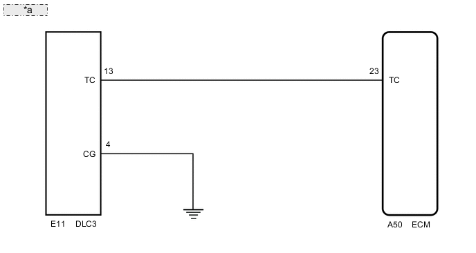
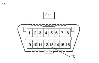
| *a | for 1NR-FE: |
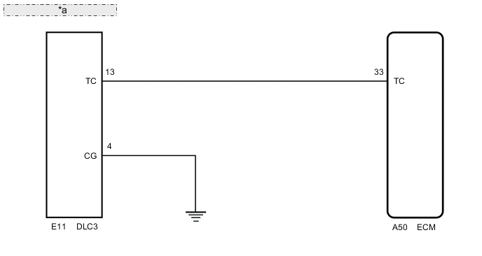
| *a | for 1ZR-FAE, 1ZR-FE, 2ZR-FE: |
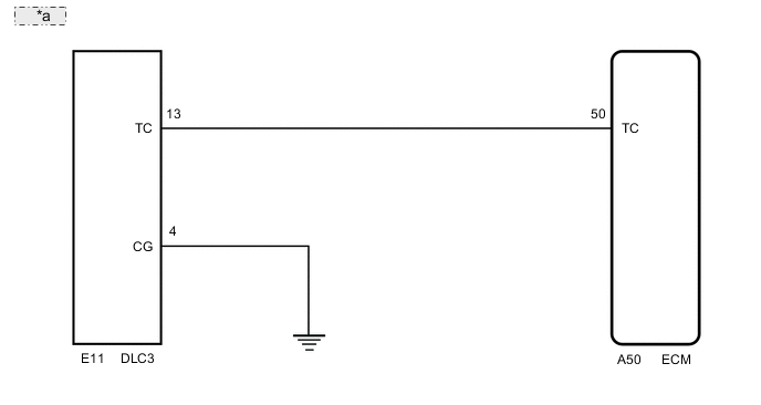
| *a | for 1WW: |
CAUTION / NOTICE / HINT
Tech Tips
When a particular warning light remains blinking, a ground short in the wiring of terminal TC of the DLC3 or an internal ground short in the relevant ECU is suspected.
PROCEDURE
-
CHECK HARNESS AND CONNECTOR (TERMINAL TC of DLC3 - ECM)
-
Disconnect the ECM connector.
-
Measure the resistance according to the value(s) in the table below.
Standard Resistance (Check for Open) for 1NR-FE Tester Connection Condition Specified Condition A50-23 (TC) - E11-13 (TC) Always Below 1 Ω for 1ZR-FAE, 1ZR-FE, 2ZR-FE Tester Connection Condition Specified Condition A50-33 (TC) - E11-13 (TC) Always Below 1 Ω for 1WW Tester Connection Condition Specified Condition A50-50 (TC) - E11-13 (TC) Always Below 1 Ω Result Proceed to OK NG
NG 
REPAIR OR REPLACE HARNESS OR CONNECTOR (DLC3 - ECM)
OK 
-
-
CHECK HARNESS AND CONNECTOR (TERMINAL CG of DLC3 - BODY GROUND)
-
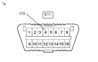
*a DLC3 Measure the resistance according to the value(s) in the table below.
Standard Resistance (Check for Open) Tester Connection Condition Specified Condition E11-4 (CG) - Body ground Always Below 1 Ω Result Proceed to OK NG
NG
REPAIR OR REPLACE HARNESS OR CONNECTOR (DLC3 - BODY GROUND)
OK
-
-
CHECK HARNESS AND CONNECTOR (TERMINAL TC of DLC3 - BODY GROUND)
-
*a DLC3 Measure the resistance according to the value(s) in the table below.
Standard Resistance (Check for Open) Tester Connection Condition Specified Condition E11-13 (TC) - Body ground Always 10 kΩ or higher Result Proceed to OK NG
OK
PROCEED TO NEXT SUSPECTED AREA SHOWN IN PROBLEM SYMPTOMS TABLE Click here
NG
REPAIR OR REPLACE HARNESS OR CONNECTOR OR EACH ECU
-