STARTER(w/o Stop And Start System) REASSEMBLY
PROCEDURE
-
INSTALL PLANET CARRIER SHAFT SUB-ASSEMBLY
-
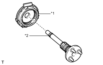
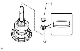
*1 Planet Carrier *2 Planet Carrier Shaft Sub-assembly Install the planet carrier shaft sub-assembly to the planet carrier.
-
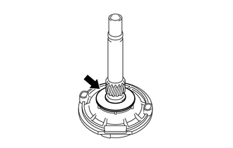
Install the washer to the planet carrier shaft sub-assembly.
-
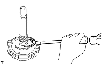
Using a screwdriver, install the snap ring to the planet carrier shaft sub-assembly.
-
-
INSTALL STARTER CLUTCH SUB-ASSEMBLY
-

High-temperature Grease Apply high-temperature grease to the spline of the starter clutch sub-assembly and planet carrier shaft sub-assembly.
-
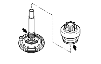
Install the starter clutch sub-assembly to the planet carrier shaft sub-assembly.
-
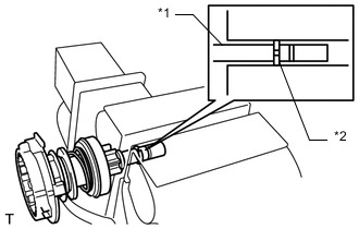
*1 Snap Ring *2 Pinion Stop Collar Install the pinion stop collar and a new snap ring.
-
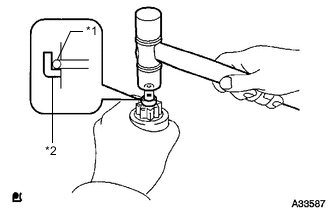
*1 Planet Carrier Shaft Sub-assembly *2 Snap Ring Using a vise, compress the snap ring.
-
*1 Snap Ring *2 Pinion Stop Collar While holding the starter clutch sub-assembly, lightly tap the planet carrier shaft sub-assembly and install the pinion stop collar onto the snap ring with a plastic hammer.
-
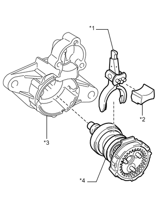
*1 Pinion Drive Lever *2 Starter Drive Housing Cover *3 Starter Drive Housing Assembly *4 Planet Carrier Shaft Sub-assembly with Starter Clutch Sub-assembly and Planet Carrier Install the planet carrier shaft sub-assembly with starter clutch sub-assembly and planet carrier, pinion drive lever and starter drive housing cover to the starter drive housing assembly.
-
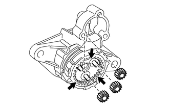
High-temperature Grease Apply high-temperature grease to the planet carrier.
-
Install the 3 planetary gears to the planet carrier shaft sub-assembly.
-
-
INSTALL STARTER ARMATURE ASSEMBLY
-
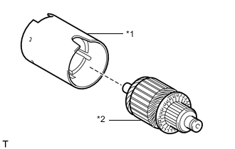
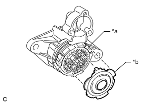
*1 Starter Yoke Assembly *2 Starter Armature Assembly Install the starter armature assembly to the starter yoke assembly.
-
-
INSTALL STARTER BRUSH HOLDER ASSEMBLY
-
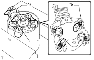
*1 Starter Brush Holder Assembly *a Rubber *b Spring *c Cutout Secure the starter yoke assembly in a vise between aluminum plates.
Note
Do not overtighten the vise.
-
While compressing the springs, install the starter brush holder assembly to the starter armature assembly.
Note
-
Align the cutout of the starter yoke assembly with the rubber and install the starter brush holder assembly.
-
Use caution to prevent the starter armature assembly from dropping.
-
-
*a Washer *b Starter Commutator End Frame Install the starter commutator end frame to the starter yoke assembly.
Note
Use caution to prevent the starter armature assembly from dropping.
-
Install the washer to the starter commutator end frame.
Note
Use caution to prevent the starter armature assembly from dropping.
-
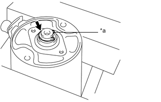
*a Slotted Washer High-temperature Grease Apply high-temperature grease to the slotted washer.
-
Install the slotted washer.
-
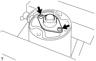
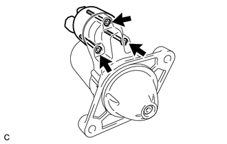
Install the starter commutator end frame cover to the starter commutator end frame with the 2 screws.
- Torque:
- 1.4 N*m { 14 kgf*cm, 12 in.*lbf }
-
-
INSTALL STARTER YOKE ASSEMBLY
-
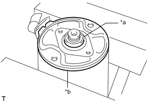
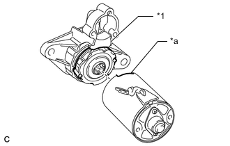
*a Planet Carrier *b Plate Install the plate to the planet carrier.
-
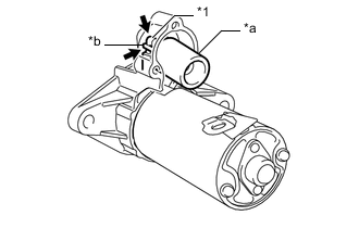
*1 Starter Drive Housing Cover *a Cutout Align the cutout of the starter yoke assembly with the starter drive housing cover.
-
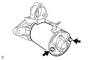
Install the starter yoke assembly to the starter drive housing with the 2 through bolts.
- Torque:
- 4.8 N*m { 49 kgf*cm, 42 in.*lbf }
-
-
INSTALL MAGNET STARTER SWITCH ASSEMBLY
-
*1 Pinion Drive Lever *a Plunger *b Hook High-temperature Grease Apply high-temperature grease to the hook and pinion drive lever.
-
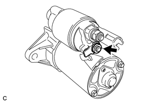
Hang the hook of the plunger on the pinion drive lever.
-
Install the return spring to the magnet switch.
-
Using a T25 "TORX" socket wrench, install the magnet switch to the starter drive housing assembly with the 3 screws.
- Torque:
- 7.0 N*m { 71 kgf*cm, 62 in.*lbf }
-
Connect the field coil lead wire to terminal C with the nut.
- Torque:
- 8.0 N*m { 82 kgf*cm, 71 in.*lbf }
-