KEY REMINDER WARNING SYSTEM Key Reminder Buzzer does not Sound
DESCRIPTION
The key reminder warning buzzer sounds when the driver door is opened while the ignition switch is off or ACC. The key reminder warning buzzer is activated when the main body ECU (multiplex network body ECU) sends an unlock warning switch signal and driver door courtesy light switch signal to the combination meter assembly via CAN communication.
WIRING DIAGRAM
-
for LHD
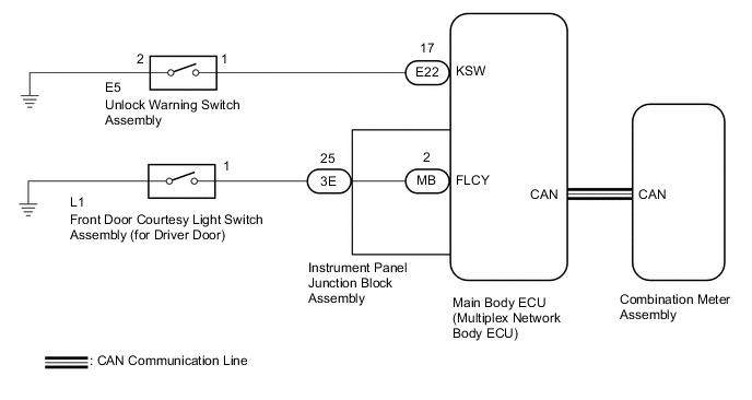
-
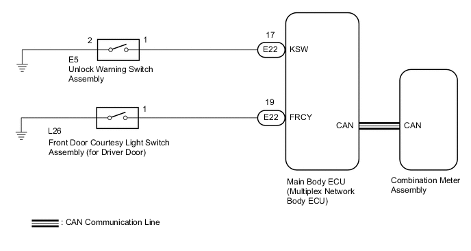
for RHD
CAUTION / NOTICE / HINT
Note
The key reminder warning system uses the CAN communication system. Inspect the communication function by following How to Proceed with Troubleshooting. Troubleshoot the key reminder warning system after confirming that the communication systems are functioning properly.
PROCEDURE
-
CHECK COMBINATION METER ASSEMBLY (BUZZER OPERATION)
-
Turn the ignition switch to ON. Place luggage on the front passenger seat to cause the front passenger seat belt warning light to blink.
-
When driving the vehicle at 20 km/h (12 mph) or higher, check that the seat belt warning buzzer sounds to inform that the front passenger seat belt is not fastened.
Tech Tips
The key reminder warning system sounds the buzzer built into the combination meter assembly as a key reminder warning. This buzzer is also used for the seat belt warning system. Therefore, check the operation of the combination meter buzzer by checking if the buzzer sounds to inform that the seat belt is not fastened.
OK Combination meter buzzer sounds. Result Proceed to OK NG
NG 
REPLACE COMBINATION METER ASSEMBLY Click here
OK 
-
-
READ VALUE USING GTS (FR Door Courtesy SW, FL Door Courtesy SW)
-
Connect the GTS to the DLC3.
-
Turn the ignition switch to ON.
-
Turn the GTS on.
-
Enter the following menus: Body Electrical / Main Body / Data List.
-
Read the Data List according to the display on the GTS.
Body Electrical > Main Body > Data ListTester Display Measurement Item Range Normal Condition Diagnostic Note FR Door Courtesy SW Front door courtesy light switch RH signal ON or OFF ON: Front door RH open
OFF: Front door RH closed
*1 FL Door Courtesy SW Front door courtesy light switch LH signal ON or OFF ON: Front door RH open
OFF: Front door RH closed
*2
-
*1: for RHD
-
*2: for LHD
Body Electrical > Main Body > Data ListTester Display FR Door Courtesy SW FL Door Courtesy SW OK The GTS indicates ON or OFF according to the driver door condition shown in the table. Result Proceed to OK NG -
NG 
INSPECT FRONT DOOR COURTESY LIGHT SWITCH ASSEMBLY (for Driver Door) Click here
OK
-
-
READ VALUE USING GTS (Key Unlock Warning SW)
-
Connect the GTS to the DLC3.
-
Turn the ignition switch to ON.
-
Turn the GTS on.
-
Enter the following menus: Body Electrical / Main Body / Data List.
-
Read the Data List according to the display on the GTS.
Body Electrical > Main Body > Data ListTester Display Measurement Item Range Normal Condition Diagnostic Note Key Unlock Warning SW Unlock warning switch signal ON or OFF ON: Key in ignition key cylinder
OFF: No key in ignition key cylinder
-
Body Electrical > Main Body > Data ListTester Display Key Unlock Warning SW OK The GTS indicates ON or OFF according to whether the key is in the ignition key cylinder. Result Proceed to OK NG
OK
REPLACE MAIN BODY ECU (MULTIPLEX NETWORK BODY ECU) for LHD: Click here
REPLACE MAIN BODY ECU (MULTIPLEX NETWORK BODY ECU) for RHD: Click hereNG
-
-
INSPECT UNLOCK WARNING SWITCH ASSEMBLY
-
Remove the unlock warning switch assembly.
-
Inspect the unlock warning switch assembly.
Result Proceed to OK NG
NG
REPLACE UNLOCK WARNING SWITCH ASSEMBLY Click here
OK
-
-
CHECK HARNESS AND CONNECTOR (UNLOCK WARNING SWITCH ASSEMBLY - MAIN BODY ECU (MULTIPLEX NETWORK BODY ECU))
-
Disconnect the E22 main body ECU (multiplex network body ECU) connector.
-
Measure the resistance according to the value(s) in the table below.
Standard Resistance Tester Connection Condition Specified Condition E5-1 - E22-17 (KSW) Always Below 1 Ω E5-2 - Body ground Always Below 1 Ω E5-1 - Body ground Always 10 kΩ or higher E22-17 (KSW) - Body ground Always 10 kΩ or higher Result Proceed to OK NG
OK
REPLACE MAIN BODY ECU (MULTIPLEX NETWORK BODY ECU) for LHD: Click here
REPLACE MAIN BODY ECU (MULTIPLEX NETWORK BODY ECU) for RHD: Click hereNG
REPAIR OR REPLACE HARNESS OR CONNECTOR
-
-
INSPECT FRONT DOOR COURTESY LIGHT SWITCH ASSEMBLY (for Driver Door)
-
Remove the front door courtesy light switch assembly (for driver door).
-
Inspect the front door courtesy light switch assembly (for driver door).
Result Result Proceed to OK (for LHD) A OK (for RHD) B NG C
B
CHECK HARNESS AND CONNECTOR (FRONT DOOR COURTESY LIGHT SWITCH ASSEMBLY (for Driver Door) - MAIN BODY ECU (MULTIPLEX NETWORK BODY ECU)) Click here
C
REPLACE FRONT DOOR COURTESY LIGHT SWITCH ASSEMBLY (for Driver Door) Click here
A
-
-
CHECK HARNESS AND CONNECTOR (FRONT DOOR COURTESY LIGHT SWITCH ASSEMBLY (for Driver Door) - INSTRUMENT PANEL JUNCTION BLOCK ASSEMBLY)
-
Disconnect the 3E instrument panel junction block assembly connector.
-
Measure the resistance according to the value(s) in the table below.
Standard Resistance Tester Connection Condition Specified Condition L1-1 - 3E-25 Always Below 1 Ω L1-1 - Body ground Always 10 kΩ or higher 3E-25 - Body ground Always 10 kΩ or higher Result Proceed to OK NG
NG
REPAIR OR REPLACE HARNESS OR CONNECTOR
OK
-
-
INSPECT INSTRUMENT PANEL JUNCTION BLOCK ASSEMBLY
-
Remove the instrument panel junction block assembly.
for LHD: Click here
for RHD: Click here
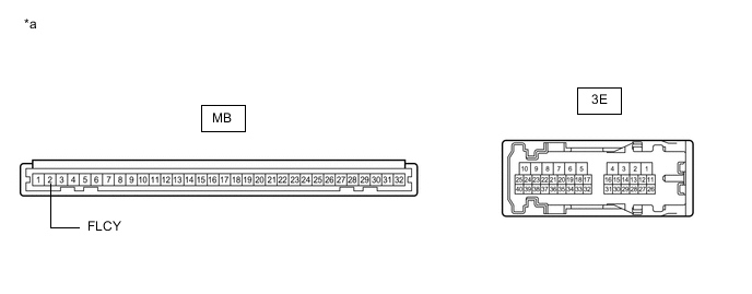
*a Component without harness connected
(Instrument Panel Junction Block Assembly)
- - -
Remove the main body ECU (multiplex network body ECU) from the instrument panel junction block assembly.
-
Measure the resistance according to the value(s) in the table below.
Standard Resistance Tester Connection Condition Specified Condition 3E-25 - MB-2 (FLCY) Always Below 1 Ω Result Proceed to OK NG
OK
REPLACE MAIN BODY ECU (MULTIPLEX NETWORK BODY ECU) Click here
NG
REPLACE INSTRUMENT PANEL JUNCTION BLOCK ASSEMBLY for LHD: Click here
REPLACE INSTRUMENT PANEL JUNCTION BLOCK ASSEMBLY for RHD: Click here -
-
CHECK HARNESS AND CONNECTOR (FRONT DOOR COURTESY LIGHT SWITCH ASSEMBLY (for Driver Door) - MAIN BODY ECU (MULTIPLEX NETWORK BODY ECU))
-
Disconnect the E22 main body ECU (multiplex network body ECU) connector.
-
Measure the resistance according to the value(s) in the table below.
Standard Resistance Tester Connection Condition Specified Condition L26-1 - E22-19 (FRCY) Always Below 1 Ω L26-1 - Body ground Always 10 kΩ or higher E22-19 (FRCY) - Body ground Always 10 kΩ or higher Result Proceed to OK NG
OK
REPLACE MAIN BODY ECU (MULTIPLEX NETWORK BODY ECU) for LHD: Click here
REPLACE MAIN BODY ECU (MULTIPLEX NETWORK BODY ECU) for RHD: Click hereNG
REPAIR OR REPLACE HARNESS OR CONNECTOR
-