POWER DOOR LOCK CONTROL SYSTEM(for Hatchback, Wagon) TERMINALS OF ECU
-
CHECK INSTRUMENT PANEL JUNCTION BLOCK ASSEMBLY AND MAIN BODY ECU (MULTIPLEX NETWORK BODY ECU)
-
Disconnect the MB main body ECU (multiplex network body ECU) connector.
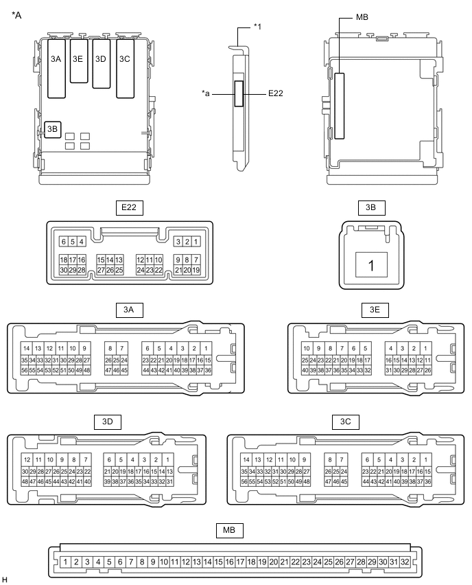
*A Main Body ECU (Multiplex Network Body ECU) with 1 Connector - - *1 Main Body ECU (Multiplex Network Body ECU) - - *a 1 Connector - - 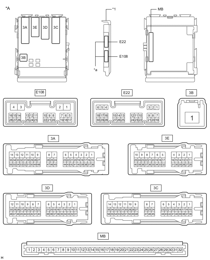
*A Main Body ECU (Multiplex Network Body ECU) with 2 Connectors - - *1 Main Body ECU (Multiplex Network Body ECU) - - *a 2 Connectors - - -
Measure the voltage and resistance according to the value(s) in the table below.
Tech Tips
Measure the values on the wire harness side with the connectors disconnected.
Tester Connection Wiring Color Terminal Description Condition Specified Condition MB-11 (GND1) - Body ground - Ground Always Below 1 Ω MB-30 (BECU) - Body ground - Battery power supply Always 11 to 14 V MB-29 (ACC) - Body ground - ACC power supply Ignition switch ACC 11 to 14 V MB-29 (ACC) - Body ground - ACC power supply Ignition switch off Below 1 V MB-32 (IG) - Body ground - Ignition switch power supply Ignition switch ON 11 to 14 V MB-32 (IG) - Body ground - Ignition switch power supply Ignition switch off Below 1 V If the result is not as specified, there may be a malfunction in the wire harness.
-
Reconnect the MB main body ECU (multiplex network body ECU) connector.
-
Measure the voltage and check for pulses according to the value(s) in the table below.
Tester Connection Wiring Color Terminal Description Condition Specified Condition 3E-1 (ACT-) - Body ground SB - Body ground Door lock motor unlock drive output (all door) Door control switch (power window regulator master switch assembly) or driver door key cylinder off Below 1 V 3E-1 (ACT-) - Body ground SB - Body ground Door lock motor unlock drive output (all door) Door control switch (power window regulator master switch assembly) or driver door key cylinder unlocked 11 to 14 V 3C-5 (ACT-) - Body ground SB - Body ground Door lock motor unlock drive output (all door) Door control switch (power window regulator master switch assembly) or driver door key cylinder off Below 1 V 3C-5 (ACT-) - Body ground SB - Body ground Door lock motor unlock drive output (all door) Door control switch (power window regulator master switch assembly) or driver door key cylinder unlocked 11 to 14 V 3E-2 (ACT-) - Body ground SB - Body ground Door lock motor unlock drive output (all door) Door control switch (power window regulator master switch assembly) or driver door key cylinder off Below 1 V 3E-2 (ACT-) - Body ground SB - Body ground Door lock motor unlock drive output (all door) Door control switch (power window regulator master switch assembly) or driver door key cylinder unlocked 11 to 14 V 3C-4 (ACT-) - Body ground LG - Body ground Door lock motor unlock drive output (all door) Door control switch (power window regulator master switch assembly) or driver door key cylinder off Below 1 V 3C-4 (ACT-) - Body ground LG - Body ground Door lock motor unlock drive output (all door) Door control switch (power window regulator master switch assembly) or driver door key cylinder unlocked 11 to 14 V 3C-13 (ACT+) - Body ground BE - Body ground Door lock motor lock drive output (all doors) Door control switch (power window regulator master switch assembly) or driver door key cylinder off Below 1 V 3C-13 (ACT+) - Body ground BE - Body ground Door lock motor lock drive output (all doors) Door control switch (power window regulator master switch assembly) or driver door key cylinder locked 11 to 14 V 3C-14 (ACT+) - Body ground R - Body ground Door lock motor lock drive output (all doors) Door control switch (power window regulator master switch assembly) or driver door key cylinder off Below 1 V 3C-14 (ACT+) - Body ground R - Body ground Door lock motor lock drive output (all doors) Door control switch (power window regulator master switch assembly) or driver door key cylinder locked 11 to 14 V 3E-8 (ACT+) - Body ground BE - Body ground Door lock motor lock drive output (all doors) Door control switch (power window regulator master switch assembly) or driver door key cylinder off Below 1 V 3E-8 (ACT+) - Body ground BE - Body ground Door lock motor lock drive output (all doors) Door control switch (power window regulator master switch assembly) or driver door key cylinder locked 11 to 14 V 3E-9 (ACT+) - Body ground R - Body ground Door lock motor lock drive output (all doors) Door control switch (power window regulator master switch assembly) or driver door key cylinder off Below 1 V 3E-9 (ACT+) - Body ground R - Body ground Door lock motor lock drive output (all doors) Door control switch (power window regulator master switch assembly) or driver door key cylinder locked 11 to 14 V E22-19 (FRCY) - Body ground V - Body ground Front door courtesy light switch RH input Front door RH open Below 1 V E22-19 (FRCY) - Body ground V - Body ground Front door courtesy light switch RH input Front door RH closed Pulse generation 3E-25 (FLCY) - Body ground W - Body ground Front door courtesy light switch LH input Front door LH open Below 1 V 3E-25 (FLCY) - Body ground W - Body ground Front door courtesy light switch LH input Front door LH closed Pulse generation E22-24 (LCTY) - Body ground SB - Body ground Rear door courtesy light switch LH input Rear door LH open Below 1 V E22-24 (LCTY) - Body ground SB - Body ground Rear door courtesy light switch LH input Rear door LH closed Pulse generation E22-6 (RCTY) - Body ground LG - Body ground Rear door courtesy light switch RH input Rear door RH open Below 1 V E22-6 (RCTY) - Body ground LG - Body ground Rear door courtesy light switch RH input Rear door RH closed Pulse generation E22-9 (L1) - Body ground*1 L - Body ground Door control switch input Door control switch locked Below 1 V E22-9 (L1) - Body ground*1 L - Body ground Door control switch input Door control switch off Pulse generation E22-10 (UL1) - Body ground*1 Y - Body ground Door control switch input Door control switch unlocked Below 1 V E22-10 (UL1) - Body ground*1 Y - Body ground Door control switch input Door control switch off Pulse generation E22-11 (L2) - Body ground SB - Body ground Driver door key-linked lock input Driver door key cylinder turned to lock position Below 1 V E22-11 (L2) - Body ground SB - Body ground Driver door key-linked lock input Driver door key cylinder off Pulse generation E22-12 (UL2) - Body ground P - Body ground Driver door key-linked unlock input Driver door key cylinder turned to unlock position Below 1 V E22-12 (UL2) - Body ground P - Body ground Driver door key-linked unlock input Driver door key cylinder off Pulse generation E22-7 (LSFL) - Body ground Y - Body ground Front door LH unlock detection switch input Front door LH unlocked Below 1 V E22-7 (LSFL) - Body ground Y - Body ground Front door LH unlock detection switch input Front door LH locked Pulse generation E22-18 (LSFR) - Body ground LG - Body ground Front door RH unlock detection switch input Front door RH unlocked Below 1 V E22-18 (LSFR) - Body ground LG - Body ground Front door RH unlock detection switch input Front door RH locked Pulse generation 3E-22 (LSR) - Body ground Y - Body ground Rear door RH unlock detection switch input Rear door RH or LH unlocked Below 1 V 3E-22 (LSR) - Body ground Y - Body ground Rear door RH unlock detection switch input Rear door RH and LH locked Pulse generation 3E-37 (LSR) - Body ground Y - Body ground Rear door LH unlock detection switch input Rear door LH or RH unlocked Below 1 V 3E-37 (LSR) - Body ground Y - Body ground Rear door LH unlock detection switch input Rear door LH and RH locked Pulse generation 3E-34 (BCTY) - Body ground LG - Body ground Back door courtesy light switch input Back door open Below 1 V 3E-34 (BCTY) - Body ground LG - Body ground Back door courtesy light switch input Back door closed 11 to 14 V 3E-39 (TR+) - Body ground P - Body ground Back door lock motor unlock drive output Back door opener switch (open switch) pushed 11 to 14 V 3E-39 (TR+) - Body ground P - Body ground Back door lock motor unlock drive output Back door opener switch (open switch) not pushed Below 1 V E22-17 (KSW) - Body ground*2 V - Body ground Key unlock warning switch input No key in ignition key cylinder Pulse generation E22-17 (KSW) - Body ground*2 V - Body ground Key unlock warning switch input Key in ignition key cylinder Below 1 V E22-23 (BDSU) - Body ground*2 V - Body ground Back door opener switch input Back door opener switch (open switch) pushed Below 1 V E22-23 (BDSU) - Body ground*2 V - Body ground Back door opener switch input Back door opener switch (open switch) not pushed Pulse generation
-
*1: for Model with Jam Protection Function on Driver Door Window Only
-
*2: w/o Entry and Start System
If the result is not as specified, the main body ECU (multiplex network body ECU) or instrument panel junction block assembly may be malfunctioning.
-
-
-
CHECK CERTIFICATION ECU (SMART KEY ECU ASSEMBLY) (w/ Entry and Start System)
-
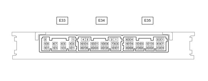
Disconnect the E33 certification ECU (smart key ECU assembly) connector.
-
Measure the voltage and resistance according to the value(s) in the table below.
Tech Tips
Measure the values on the wire harness side with the connector disconnected.
Tester Connection Wiring Color Terminal Description Condition Specified Condition E33-11 (E) - Body ground W-B - Body ground Ground Always Below 1 Ω E33-2 (+B) - Body ground L - Body ground +B power supply Always 11 to 14 V If the result is not as specified, there may be a malfunction in the wire harness.
-
Reconnect the E33 certification ECU (smart key ECU assembly) connector.
-
Measure the voltage according to the value(s) in the table below.
Tester Connection Wiring Color Terminal Description Condition Specified Condition E34-27 (TSW5) - Body ground V - Body ground Back door opener switch signal Back door opener switch off Pulse generation E34-27 (TSW5) - Body ground V - Body ground Back door opener switch signal Back door opener switch on Below 1 V If the result is not as specified, the certification ECU (smart key ECU assembly) may be malfunctioning.
-
-
CHECK DOUBLE LOCK DOOR CONTROL RELAY ASSEMBLY (w/ Double Locking System)
-
Disconnect the E107 double lock door control relay assembly connector.

-
Measure the voltage and resistance according to the value(s) in the table below.
Tech Tips
Measure the values on the wire harness side with the connector disconnected.
Tester Connection Wiring Color Terminal Description Condition Specified Condition E107-1 (+B) - Body ground B - Body ground Battery power supply Always 11 to 14 V E107-7 (CPUB) - Body ground LG - Body ground Battery power supply Always 11 to 14 V E107-14 (GND) - Body ground W-B - Body ground Ground Always Below 1 Ω If the result is not as specified, there may be a malfunction in the wire harness.
-
Reconnect the E107 double lock door control relay assembly connector.
-
Measure the voltage according to the value(s) in the table below.
Tester Connection Wiring Color Terminal Description Condition Specified Condition E107-5 (DLPD) - Body ground GR - Body ground Front RH double lock position switch input Double lock unset Pulse generation E107-5 (DLPD) - Body ground GR - Body ground Front RH double lock position switch input Double lock set Below 1 V E107-6 (DLPP) - Body ground L - Body ground Front LH double lock position switch input Double lock unset Pulse generation E107-6 (DLPP) - Body ground L - Body ground Front LH double lock position switch input Double lock set Below 1 V E107-11 (DLPR) - Body ground L - Body ground Rear RH double lock position switch input Double lock unset Pulse generation E107-11 (DLPR) - Body ground L - Body ground Rear RH double lock position switch input Double lock set Below 1 V E107-12 (DLPL) - Body ground P - Body ground Rear LH double lock position switch input Double lock unset Pulse generation E107-12 (DLPL) - Body ground P - Body ground Rear LH double lock position switch input Double lock set Below 1 V E107-3 (ACTS) - Body ground R - Body ground All door double lock motor set on output Double lock unset Below 1 V E107-3 (ACTS) - Body ground R - Body ground All door double lock motor set on output Double lock set 11 to 14 V E107-4 (ACTR) - Body ground G - Body ground All door double lock motor set off output Double lock set Below 1 V E107-4 (ACTR) - Body ground G - Body ground All door double lock motor set off output Double lock unset 11 to 14 V If the result is not as specified, the double lock door control relay assembly may be malfunctioning.
-