CAN COMMUNICATION SYSTEM(w/o Central Gateway ECU) TERMINALS OF ECU
Note
-
After turning the ignition switch off, waiting time may be required before disconnecting the cable from the negative (-) battery terminal. Therefore, make sure to read the disconnecting the cable from the negative (-) battery terminal notices before proceeding with work.
-
Turn the ignition switch off before measuring the resistances between CAN main bus lines and between CAN branch lines.
-
Turn the ignition switch off before inspecting CAN bus lines for a short to ground.
-
Before measuring the resistance of the CAN bus, turn the ignition switch off and leave the vehicle for 1 minute or more without operating the key or any switches, or opening or closing the doors. After that, disconnect the cable from the negative (-) battery terminal and leave the vehicle for 1 minute or more before measuring the resistance.
-
This section describes the standard values for all CAN related components.
Tech Tips
-
Operating the ignition switch, any other switches or a door triggers related ECU and sensor communication on the CAN. This communication will cause the resistance value to change.
-
Even after DTCs are cleared, if a DTC is stored again after driving the vehicle for a while, the malfunction may be occurring due to vibration of the vehicle. In such a case, wiggling the ECUs or wire harness while performing the inspection below may help determine the cause of the malfunction.
-
NO. 1 CAN JUNCTION CONNECTOR (for LHD Sedan)
-
Check the No. 1 CAN junction connector.
-
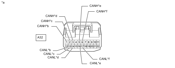
Connection diagram
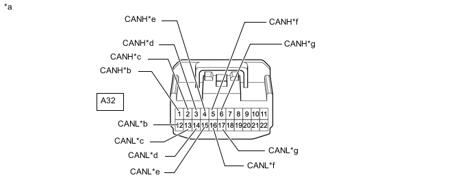
*a Front view of wire harness connector
(to No. 1 CAN Junction Connector)
*b to No. 3 CAN Junction Connector *c to DLC3 *d to Main Body ECU (Multiplex Network Body ECU) *e
-
to Headlight Leveling ECU Assembly
(for Sedan with Automatic Headlight Beam Level Control System)
-
to Headlight Swivel ECU Assembly
(except Sedan with Automatic Headlight Beam Level Control System)
*f to Brake Actuator Assembly *g to ECM - - -
-
Check the connection diagram of the components which are connected to the No. 1 CAN junction connector.
Terminal No. (Symbol) Wiring Color Connected to A32-1 (CANH) L No. 3 CAN junction connector A32-12 (CANL) W A32-2 (CANH) R DLC3 A32-13 (CANL) W A32-3 (CANH) G Main body ECU (multiplex network body ECU) A32-14 (CANL) W A32-4 (CANH) Y
-
Headlight leveling ECU assembly*1
-
Headlight swivel ECU assembly*2
A32-15 (CANL) W A32-5 (CANH) V Brake actuator assembly A32-16 (CANL) W A32-6 (CANH) B ECM A32-17 (CANL) W
-
*1: for Sedan with Automatic Headlight Beam Level Control System
-
*2: except Sedan with Automatic Headlight Beam Level Control System
-
-
-
-
NO. 3 CAN JUNCTION CONNECTOR (for LHD Sedan)
-
Check the No. 3 CAN junction connector.
-
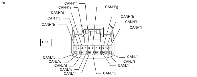
Connection diagram
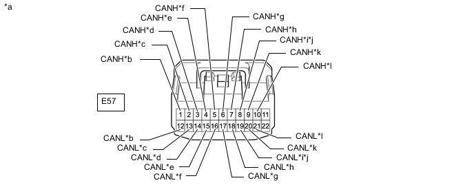
*a Front view of wire harness connector
(to No. 3 CAN Junction Connector)
*b to Airbag Sensor Assembly *c to Air Conditioning Amplifier Assembly
(w/ Air Conditioning System)
*d to Radio and Display Receiver Assembly
(for Radio and Display Type)
*e to Combination Meter Assembly *f to No. 1 CAN Junction Connector *g to Certification ECU (Smart Key ECU Assembly)
(w/ Entry and Start System)
*h to Clearance Warning ECU Assembly
(w/ Simple Intelligent Parking Assist System)
*i to Engine Stop and Start ECU
(w/ Stop and Start System)
*j to Telematics Transceiver
(w/ Manual (SOS) Switch)
*k to Power Steering ECU Assembly *l to Steering Sensor (Spiral Cable with Sensor Sub-assembly)
(w/ VSC)
-
Check the connection diagram of the components which are connected to the No. 3 CAN junction connector.
Terminal No. (Symbol) Wiring Color Connected to E57-1 (CANH) V Airbag sensor assembly E57-12 (CANL) W E57-2 (CANH) Y Air conditioning amplifier assembly*1 E57-13 (CANL) W E57-3 (CANH) Y Radio and display receiver assembly*2 E57-14 (CANL) W E57-4 (CANH) LG Combination meter assembly E57-15 (CANL) W E57-5 (CANH) L No. 1 CAN junction connector E57-16 (CANL) W E57-6 (CANH) R Certification ECU (smart key ECU assembly)*3 E57-17 (CANL) W E57-7 (CANH) B Clearance warning ECU assembly*4 E57-18 (CANL) W E57-8 (CANH) P Engine stop and start ECU*5 E57-19 (CANL) W E57-8 (CANH) G Telematics transceiver*6 E57-19 (CANL) W E57-9 (CANH) GR Power steering ECU assembly E57-20 (CANL) W E57-10 (CANH) SB Steering sensor (spiral cable with sensor sub-assembly)*7 E57-21 (CANL) W
-
*1: w/ Air Conditioning System
-
*2: for Radio and Display Type
-
*3: w/ Entry and Start System
-
*4: w/ Simple Intelligent Parking Assist System
-
*5: w/ Stop and Start System
-
*6: w/ Manual (SOS) Switch
-
*7: w/ VSC
-
-
-
-
NO. 3 CAN JUNCTION CONNECTOR (for LHD except Sedan)
-
Check the No. 3 CAN junction connector.
-
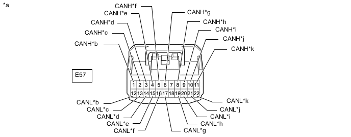
Connection diagram
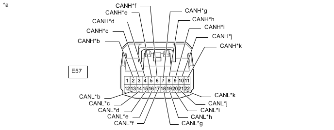
*a Front view of wire harness connector
(to No. 3 CAN Junction Connector)
*b to Air Conditioning Amplifier Assembly
(w/ Automatic Air Conditioning System)
*c to Radio and Display Receiver Assembly
(for Radio and Display Type)
*d to Combination Meter Assembly *e to No. 4 CAN Junction Connector *f to Certification ECU (Smart Key ECU Assembly)
(w/ Entry and Start System)
*g to Airbag Sensor Assembly *h to Engine Stop and Start ECU
(w/ Stop and Start System)
*i to Power Steering ECU Assembly *j to Steering Sensor (Spiral Cable with Sensor Sub-assembly) *k to Pre-crash Safety City Sensor
(w/ Toyota Safety Sense)
- - -
Check the connection diagram of the components which are connected to the No. 3 CAN junction connector.
Terminal No. (Symbol) Wiring Color Connected to E57-2 (CANH) Y Air conditioning amplifier assembly*1 E57-13 (CANL) W E57-3 (CANH) G Radio and display receiver assembly*2 E57-14 (CANL) W E57-4 (CANH) LG Combination meter assembly E57-15 (CANL) W E57-5 (CANH) L No. 4 CAN junction connector E57-16 (CANL) W E57-6 (CANH) R Certification ECU (smart key ECU assembly)*3 E57-17 (CANL) W E57-7 (CANH) V Airbag sensor assembly E57-18 (CANL) W E57-8 (CANH) P Engine stop and start ECU*4 E57-19 (CANL) W E57-9 (CANH) GR Power steering ECU assembly E57-20 (CANL) W E57-10 (CANH) SB Steering sensor (spiral cable with sensor sub-assembly) E57-21 (CANL) W E57-11 (CANH) P Pre-crash safety city sensor*5 E57-22 (CANL) W
-
*1: w/ Automatic Air Conditioning System
-
*2: for Radio and Display Type
-
*3: w/ Entry and Start System
-
*4: w/ Stop and Start System
-
*5: w/ Toyota Safety Sense
-
-
-
-
NO. 4 CAN JUNCTION CONNECTOR (for LHD except Sedan)
-
Check the No. 4 CAN junction connector.
-
Connection diagram
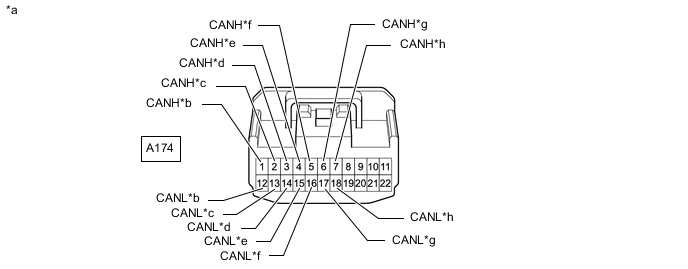
*a Front view of wire harness connector
(to No. 4 CAN Junction Connector)
*b to No. 3 CAN Junction Connector *c to DLC3 *d to Main Body ECU (Multiplex Network Body ECU) *e to Headlight Swivel ECU Assembly
(w/ Automatic Headlight Beam Level Control System)
*f to Brake Actuator Assembly *g to ECM *h to Clearance Warning ECU Assembly
(w/ Simple Intelligent Parking Assist System)
-
Check the connection diagram of the components which are connected to the No. 4 CAN junction connector.
Terminal No. (Symbol) Wiring Color Connected to A174-1 (CANH) L No. 3 CAN junction connector A174-12 (CANL) W A174-2 (CANH) R DLC3 A174-13 (CANL) W A174-3 (CANH) G Main body ECU (multiplex network body ECU) A174-14 (CANL) W A174-4 (CANH) Y Headlight swivel ECU assembly*1 A174-15 (CANL) W A174-5 (CANH) V Brake actuator assembly A174-16 (CANL) W A174-6 (CANH) B ECM A174-17 (CANL) W A174-7 (CANH) B Clearance warning ECU assembly*2 A174-18 (CANL) W
-
*1: w/ Automatic Headlight Beam Level Control System
-
*2: w/ Simple Intelligent Parking Assist System
-
-
-
-
NO. 1 CAN JUNCTION CONNECTOR (for RHD Sedan)
-
Check the No. 1 CAN junction connector.
-
Connection diagram
*a Front view of wire harness connector
(to No. 1 CAN Junction Connector)
*b to No. 3 CAN Junction Connector *c to Engine Stop and Start ECU
(w/ Stop and Start System)
*d to Main Body ECU (Multiplex Network Body ECU) *e to Brake Actuator Assembly *f to ECM -
Check the connection diagram of the components which are connected to the No. 1 CAN junction connector.
Terminal No. (Symbol) Wiring Color Connected to A32-1 (CANH) L No. 3 CAN junction connector A32-12 (CANL) W A32-2 (CANH) P Engine stop and start ECU* A32-13 (CANL) W A32-3 (CANH) G Main body ECU (multiplex network body ECU) A32-14 (CANL) W A32-5 (CANH) V Brake actuator assembly A32-16 (CANL) W A32-6 (CANH) B ECM A32-17 (CANL) W
-
*: w/ Stop and Start System
-
-
-
-
NO. 3 CAN JUNCTION CONNECTOR (for RHD Sedan)
-
Check the No. 3 CAN junction connector.
-
Connection diagram
*a Front view of wire harness connector
(to No. 3 CAN Junction Connector)
*b to Airbag Sensor Assembly *c to Air Conditioning Amplifier Assembly
(w/ Air Conditioning System)
*d to Radio and Display Receiver Assembly
(for Radio and Display Type)
*e to Combination Meter Assembly *f to No. 1 CAN Junction Connector *g to Certification ECU (Smart Key ECU Assembly)
(w/ Entry and Start System)
*h to Power Steering ECU Assembly *i to Steering Sensor (Spiral Cable with Sensor Sub-assembly) *j to DLC3 -
Check the connection diagram of the components which are connected to the No. 3 CAN junction connector.
Terminal No. (Symbol) Wiring Color Connected to E57-1 (CANH) V Airbag sensor assembly E57-12 (CANL) W E57-2 (CANH) Y Air conditioning amplifier assembly*1 E57-13 (CANL) W E57-3 (CANH) Y Radio and display receiver assembly*2 E57-14 (CANL) W E57-4 (CANH) LG Combination meter assembly E57-15 (CANL) W E57-5 (CANH) L No. 1 CAN junction connector E57-16 (CANL) W E57-6 (CANH) R Certification ECU (smart key ECU assembly)*3 E57-17 (CANL) W E57-9 (CANH) GR Power steering ECU assembly E57-20 (CANL) W E57-10 (CANH) SB Steering sensor (spiral cable with sensor sub-assembly) E57-21 (CANL) W E57-11 (CANH) BE DLC3 E57-22 (CANL) W
-
*1: w/ Air Conditioning System
-
*2: for Radio and Display Type
-
*3: w/ Entry and Start System
-
-
-
-
NO. 3 CAN JUNCTION CONNECTOR (for RHD except Sedan)
-
Check the No. 3 CAN junction connector.
-
Connection diagram
*a Front view of wire harness connector
(to No. 3 CAN Junction Connector)
*b to Airbag Sensor Assembly *c to Air Conditioning Amplifier Assembly
(w/ Automatic Air Conditioning System)
*d to Radio and Display Receiver Assembly
(for Radio and Display Type)
*e to Combination Meter Assembly *f to No. 4 CAN Junction Connector *g to Certification ECU (Smart Key ECU Assembly)
(w/ Entry and Start System)
*h to Pre-crash Safety City Sensor
(w/ Toyota Safety Sense)
*i to Power Steering ECU Assembly *j to Steering Sensor (Spiral Cable with Sensor Sub-assembly) *k to DLC3 - - -
Check the connection diagram of the components which are connected to the No. 3 CAN junction connector.
Terminal No. (Symbol) Wiring Color Connected to E57-1 (CANH) V Airbag sensor assembly E57-12 (CANL) W E57-2 (CANH) Y Air conditioning amplifier assembly*1 E57-13 (CANL) W E57-3 (CANH) G Radio and display receiver assembly*2 E57-14 (CANL) W E57-4 (CANH) LG Combination meter assembly E57-15 (CANL) W E57-5 (CANH) L No. 4 CAN junction connector E57-16 (CANL) W E57-6 (CANH) R Certification ECU (smart key ECU assembly)*3 E57-17 (CANL) W E57-8 (CANH) P Pre-crash safety city sensor*4 E57-19 (CANL) W E57-9 (CANH) GR Power steering ECU assembly E57-20 (CANL) W E57-10 (CANH) SB Steering sensor (spiral cable with sensor sub-assembly) E57-21 (CANL) W E57-11 (CANH) BE DLC3 E57-22 (CANL) W
-
*1: w/ Automatic Air Conditioning System
-
*2: for Radio and Display Type
-
*3: w/ Entry and Start System
-
*4: w/ Toyota Safety Sense
-
-
-
-
NO. 4 CAN JUNCTION CONNECTOR (for RHD except Sedan)
-
Check the No. 4 CAN junction connector.
-
Connection diagram

*a Front view of wire harness connector
(to No. 4 CAN Junction Connector)
*b to No. 3 CAN Junction Connector *c to Engine Stop and Start ECU
(w/ Stop and Start System)
*d to Main Body ECU (Multiplex Network Body ECU) *e to Headlight Swivel ECU Assembly
(w/ Automatic Headlight Beam Level Control System)
*f to Brake Actuator Assembly *g to ECM *h to Clearance Warning ECU Assembly
(w/ Simple Intelligent Parking Assist System)
-
Check the connection diagram of the components which are connected to the No. 4 CAN junction connector.
Terminal No. (Symbol) Wiring Color Connected to A174-1 (CANH) L No. 3 CAN junction connector A174-12 (CANL) W A174-2 (CANH) P Engine stop and start ECU*1 A174-13 (CANL) W A174-3 (CANH) G Main body ECU (multiplex network body ECU) A174-14 (CANL) W A174-4 (CANH) Y Headlight swivel ECU assembly*2 A174-15 (CANL) W A174-5 (CANH) V Brake actuator assembly A174-16 (CANL) W A174-6 (CANH) B ECM A174-17 (CANL) W A174-7 (CANH) B Clearance warning ECU assembly*3 A174-18 (CANL) W
-
*1: w/ Stop and Start System
-
*2: w/ Automatic Headlight Beam Level Control System
-
*3: w/ Simple Intelligent Parking Assist System
-
-
-
-
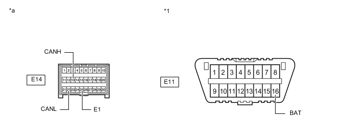
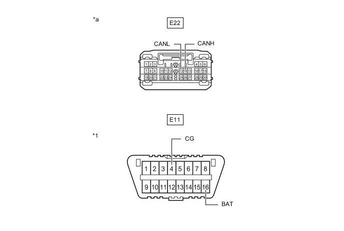
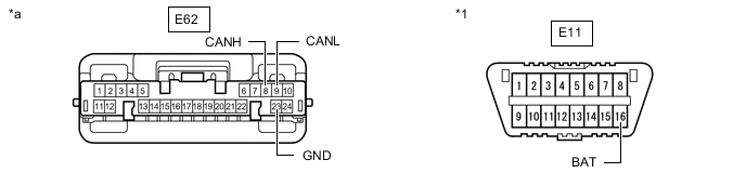
DLC3
-
Disconnect the cable from the negative (-) battery terminal.
-
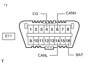
*1 DLC3 Measure the resistance according to the value(s) in the table below.
-
*1: for LHD
-
*2: for RHD
-
-
-
ECM (for 1NR-FE)
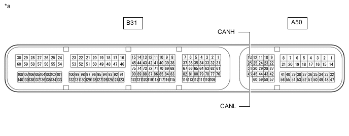
*a Component without harness connected
(ECM)
- -
-
Disconnect the cable from the negative (-) battery terminal.
-
Disconnect the A50 and B31 ECM connectors.
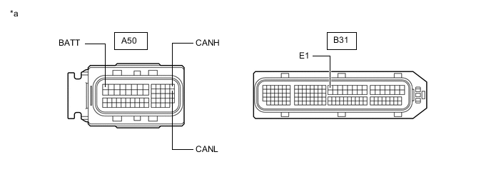
*a Front view of wire harness connector
(to ECM)
- - -
Measure the resistance according to the value(s) in the table below.
-
-
ECM (for 1ZR-FAE, 1ZR-FE or 2ZR-FE)
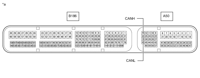
*a Component without harness connected
(ECM)
- -
-
Disconnect the cable from the negative (-) battery terminal.
-
Disconnect the A50 and B186 ECM connectors.
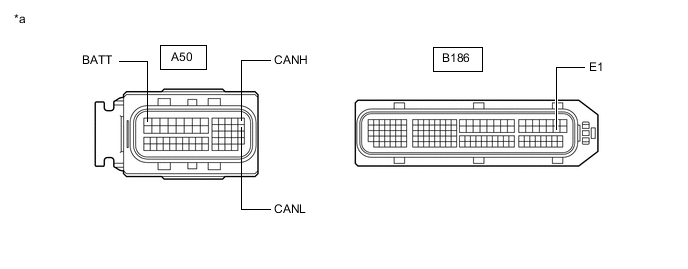
*a Front view of wire harness connector
(to ECM)
- - -
Measure the resistance according to the value(s) in the table below.
-
-
ECM (for 1ND-TV with Glow Plug Controller)
-
Disconnect the cable from the negative (-) battery terminal.
-
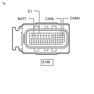
*a Front view of wire harness connector
(to ECM)
Disconnect the A169 ECM connector.
-
Measure the resistance according to the value(s) in the table below.
-
-
ECM (for 8NR-FTS)
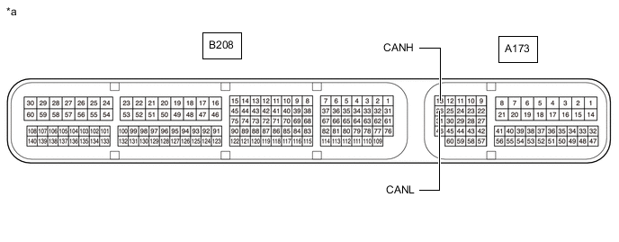
*a Component without harness connected
(ECM)
- -
-
Disconnect the cable from the negative (-) battery terminal.
-
Disconnect the A173 and B208 ECM connectors.
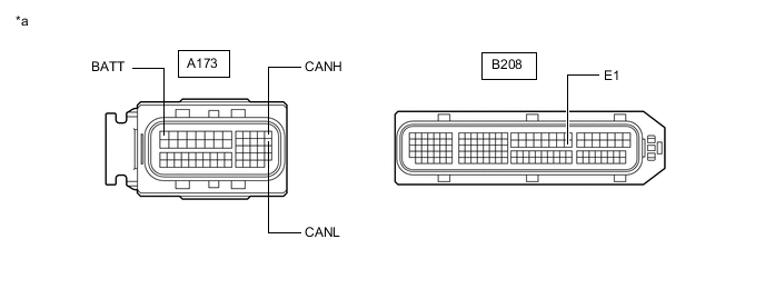
*a Front view of wire harness connector
(to ECM)
- - -
Measure the resistance according to the value(s) in the table below.
-
-
ECM (for 1WW)
-
Disconnect the cable from the negative (-) battery terminal.
-
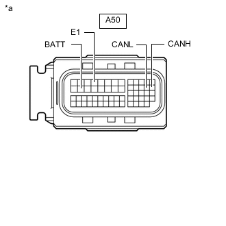
*a Front view of wire harness connector
(to ECM)
Disconnect the A50 ECM connector.
-
Measure the resistance according to the value(s) in the table below.
-
-
BRAKE ACTUATOR ASSEMBLY (w/ VSC)
-
Disconnect the cable from the negative (-) battery terminal.
-
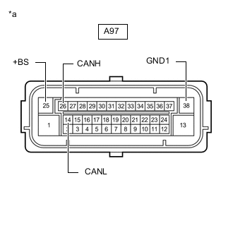
*a Front view of wire harness connector
(to Brake Actuator Assembly)
Disconnect the A97 brake actuator assembly connector.
-
Measure the resistance according to the value(s) in the table below.
-
-
BRAKE ACTUATOR ASSEMBLY (w/o VSC)
-
Disconnect the cable from the negative (-) battery terminal.
-

*a Front view of wire harness connector
(to Brake Actuator Assembly)
Disconnect the A120 brake actuator assembly connector.
-
Measure the resistance according to the value(s) in the table below.
-
-
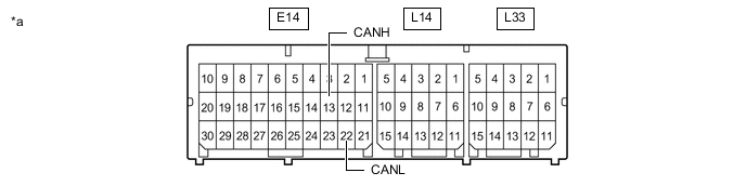
AIRBAG SENSOR ASSEMBLY
*a Component without harness connected
(Airbag Sensor Assembly)
- -
-
Disconnect the cable from the negative (-) battery terminal.
-
Disconnect the E14 airbag sensor assembly connector.
*1 DLC3 - - *a Front view of wire harness connector
(to Airbag Sensor Assembly)
- - -
Measure the resistance according to the value(s) in the table below.
-
-
INSTRUMENT PANEL JUNCTION BLOCK ASSEMBLY AND MAIN BODY ECU (MULTIPLEX NETWORK BODY ECU)
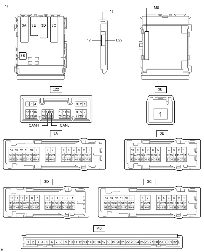
*1 Main Body ECU (Multiplex Network Body ECU) *2 1 Connector *a Component without harness connected
(Instrument Panel Junction Block Assembly and Main Body ECU (Multiplex Network Body ECU))
- - 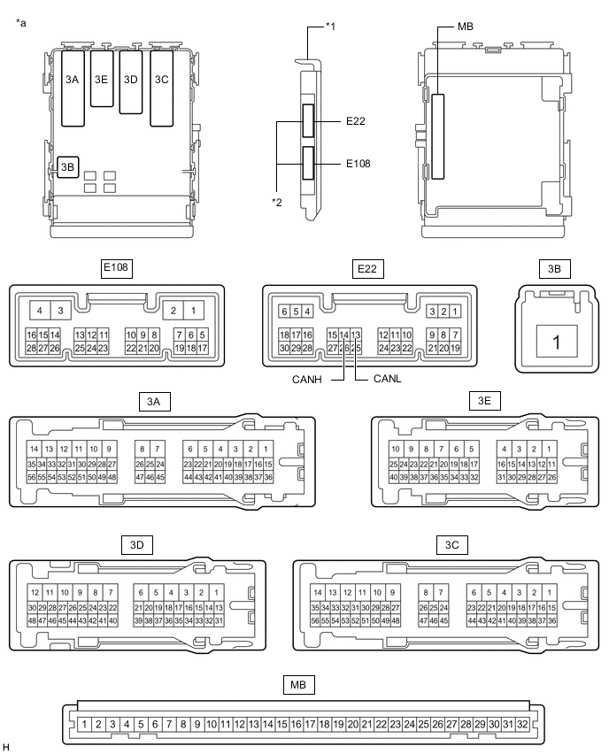
*1 Main Body ECU (Multiplex Network Body ECU) *2 2 Connectors *a Component without harness connected
(Instrument Panel Junction Block Assembly and Main Body ECU (Multiplex Network Body ECU))
- -
-
Disconnect the cable from the negative (-) battery terminal.
-
Disconnect the E22 main body ECU (multiplex network body ECU) connector.
*1 DLC3 - - *a Front view of wire harness connector
(to Main Body ECU (Multiplex Network Body ECU))
- - -
Measure the resistance according to the value(s) in the table below.
-
-
STEERING SENSOR (SPIRAL CABLE WITH SENSOR SUB-ASSEMBLY) (w/ VSC)
-
Disconnect the cable from the negative (-) battery terminal.
-
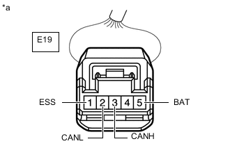
*a Front view of wire harness connector
(to Steering Sensor (Spiral Cable with Sensor Sub-assembly))
Disconnect the E19 steering sensor (spiral cable with sensor sub-assembly) connector.
-
Measure the resistance according to the value(s) in the table below.
-
-
POWER STEERING ECU ASSEMBLY
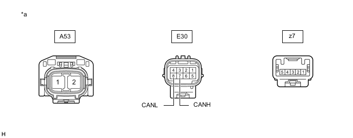
*a Component without harness connected
(Power Steering ECU Assembly)
- -
-
Disconnect the cable from the negative (-) battery terminal.
-
Disconnect the A53 and E30 power steering ECU assembly connectors.
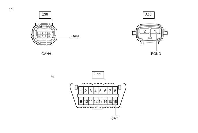
*1 DLC3 - - *a Front view of wire harness connector
(to Power Steering ECU Assembly)
- - -
Measure the resistance according to the value(s) in the table below.
-
-
CERTIFICATION ECU (SMART KEY ECU ASSEMBLY) (w/ Entry and Start System)
-
Disconnect the cable from the negative (-) battery terminal.
-
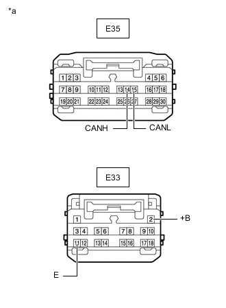
*a Front view of wire harness connector
(to Certification ECU (Smart Key ECU Assembly))
Disconnect the E33 and E35 certification ECU (smart key ECU assembly) connectors.
-
Measure the resistance according to the value(s) in the table below.
-
-
COMBINATION METER ASSEMBLY
-
Disconnect the cable from the negative (-) battery terminal.
-
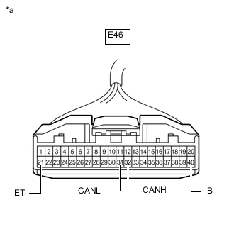
*a Front view of wire harness connector
(to Combination Meter Assembly)
Disconnect the E46 combination meter assembly connector.
-
Measure the resistance according to the value(s) in the table below.
-
-
AIR CONDITIONING AMPLIFIER ASSEMBLY (w/ Automatic Air Conditioning System)
-
Disconnect the cable from the negative (-) battery terminal.
-
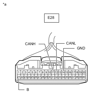
*a Front view of wire harness connector
(to Air Conditioning Amplifier Assembly)
Disconnect the E28 air conditioning amplifier assembly connector.
-
Measure the resistance according to the value(s) in the table below.
-
-
AIR CONDITIONING AMPLIFIER ASSEMBLY (w/Manual Air Conditioning System)
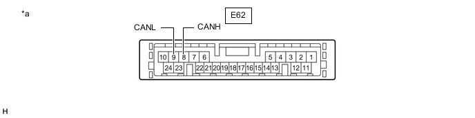
*a Component without harness connected
(Air Conditioning Amplifier Assembly)
- -
-
Disconnect the cable from the negative (-) battery terminal.
-
Disconnect the E62 air conditioning amplifier assembly connector.
*1 DLC3 - - *a Front view of wire harness connector
(to Air Conditioning Amplifier Assembly)
- - -
Measure the resistance according to the value(s) in the table below.
-
-
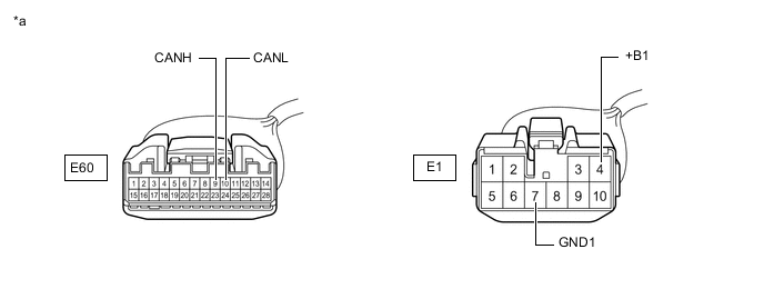
RADIO AND DISPLAY RECEIVER ASSEMBLY (for Radio and Display Type without Navigation System)
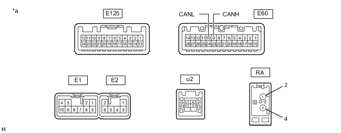
*a Component without harness connected
(Radio and Display Receiver Assembly)
- -
-
Disconnect the cable from the negative (-) battery terminal.
-
Disconnect the E1 and E60 radio and display receiver assembly connectors.

*a Front view of wire harness connector
(to Radio and Display Receiver Assembly)
- - -
Measure the resistance according to the value(s) in the table below.
-
*1: except Sedan
-
*2: for Sedan
-
-
-
RADIO AND DISPLAY RECEIVER ASSEMBLY (for Radio and Display Type with Navigation System)
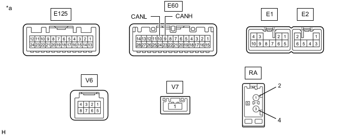
*a Component without harness connected
(Radio and Display Receiver Assembly)
- -
-
Disconnect the cable from the negative (-) battery terminal.
-
Disconnect the E1 and E60 radio and display receiver assembly connectors.
*a Front view of wire harness connector
(to Radio and Display Receiver Assembly)
- - -
Measure the resistance according to the value(s) in the table below.
-
*1: except Sedan
-
*2: for Sedan
-
-
-
ENGINE STOP AND START ECU (w/ Stop and Start System)
-
Disconnect the cable from the negative (-) battery terminal.
-
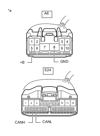
*a Front view of wire harness connector
(to Engine Stop and Start ECU)
Disconnect the A8 and E24 engine stop and start ECU connectors.
-
Measure the resistance according to the value(s) in the table below.
-
-
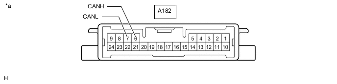
HEADLIGHT LEVELING ECU ASSEMBLY (for Sedan with Automatic Headlight Beam Level Control System)
*a Component without harness connected
(Headlight Leveling ECU Assembly)
- -
-
Disconnect the cable from the negative (-) battery terminal.
-
Disconnect the A182 headlight leveling ECU assembly connector.
*1 DLC3 - - *a Front view of wire harness connector
(to Headlight Leveling ECU Assembly)
- - -
Measure the resistance according to the value(s) in the table below.
-
-
HEADLIGHT SWIVEL ECU ASSEMBLY (except Sedan with Automatic Headlight Beam Level Control System)
-
Disconnect the cable from the negative (-) battery terminal.
-
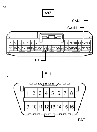
*1 DLC3 *a Front view of wire harness connector
(to Headlight Swivel ECU Assembly)
Disconnect the A93 headlight swivel ECU assembly connector.
-
Measure the resistance according to the value(s) in the table below.
-
-
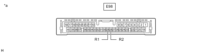
CLEARANCE WARNING ECU ASSEMBLY (w/ Simple Intelligent Parking Assist System)
*a Component without harness connected
(Clearance Warning ECU Assembly)
- -
-
Disconnect the cable from the negative (-) battery terminal.
-
Disconnect the E98 clearance warning ECU assembly connector.
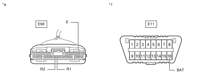
*1 DLC3 - - *a Front view of wire harness connector
(to Clearance Warning ECU Assembly)
- - -
Measure the resistance according to the value(s) in the table below.
-
-
PRE-CRASH SAFETY CITY SENSOR (w/ Toyota Safety Sense)
-
Disconnect the cable from the negative (-) battery terminal.
-
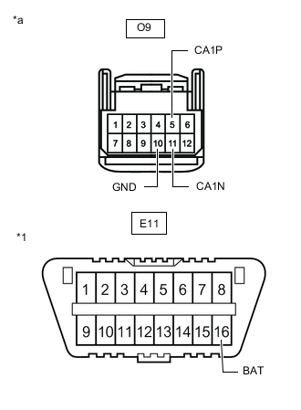
*1 DLC3 *a Front view of wire harness connector
(to Pre-crash Safety City Sensor)
Disconnect the O9 pre-crash safety city sensor connector.
-
Measure the resistance according to the value(s) in the table below.
-
-
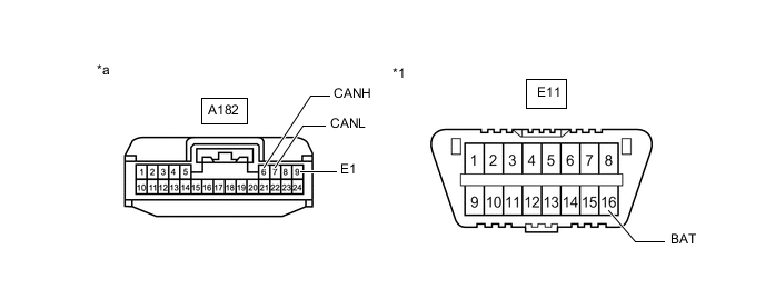
TELEMATICS TRANSCEIVER (w/ Manual (SOS) Switch)
-
Disconnect the cable from the negative (-) battery terminal.
-
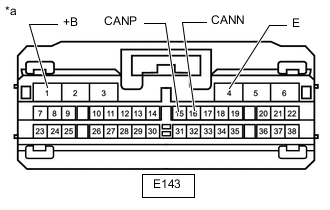
*a Front view of wire harness connector
(to Telematics Transceiver)
Disconnect the E143 telematics transceiver connector.
-
Measure the resistance according to the value(s) in the table below.
-