CHARGING SYSTEM, Diagnostic DTC:P1550, P1551, P1552
| DTC Code | DTC Name |
|---|---|
| P1550 | Battery Current Sensor Circuit |
| P1551 | Battery Current Sensor Circuit Low |
| P1552 | Battery Current Sensor Circuit High |
DESCRIPTION
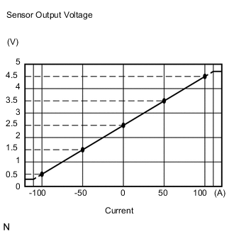
The battery current sensor assembly installed on the negative (-) battery terminal detects the amount of current supplied from the generator.
The battery current sensor assembly changes current to voltage (at the negative (-) battery terminal) and sends it to the ECM. The ECM controls the voltage of the generator based on the signals from the battery current sensor assembly.
| DTC No. | Detection Item | DTC Detection Condition | Trouble Area | Warning Indicate | Memory | Note |
|---|---|---|---|---|---|---|
| P1550 | Battery Current Sensor Circuit | Difference between the maximum and minimum current values of the battery current sensor is less than 1 A for 10 seconds or more with the ignition switch ON (1 trip detection logic) |
|
Charge warning light does not come on | DTC stored | w/ Battery Current Sensor |
| P1551 | Battery Current Sensor Circuit Low | Battery current sensor output value is less than 0.2 V for 0.5 seconds or more with the ignition switch ON (1 trip detection logic) |
|
Charge warning light does not come on | DTC stored | w/ Battery Current Sensor |
| P1552 | Battery Current Sensor Circuit High | Battery current sensor output value is higher than 4.8 V for 0.5 seconds or more with the ignition switch ON (1 trip detection logic) |
|
Charge warning light does not come on | DTC stored | w/ Battery Current Sensor |
CAUTION / NOTICE / HINT
Note
Before replacing the ECM, refer to Service Bulletin.
PROCEDURE
-
CHECK ANY OTHER DTCS OUTPUT (IN ADDITION TO DTC P1550, P1551 OR P1552)
-
Connect the GTS to the DLC3.
-
Turn the ignition switch to ON.
-
Turn the GTS on.
-
Enter the following menus: Powertrain / Engine and ECT / Trouble Codes.
-
Read the DTCs.
Powertrain > Engine and ECT > Trouble CodesResult Result Proceed to DTC P1550, P1551 or P1552 is output. A DTC P1550, P1551 or P1552 and other DTCs are output. B Tech Tips
If any DTCs other than P1550, P1551 or P1552 are output, troubleshoot those DTCs first.
B 
GO TO DTC CHART Click here
A 
-
-
READ VALUE USING GTS (BATTERY CURRENT)
-
Turn all of the electrical systems (headlights, blower motor, rear defogger, etc.) off.
-
Connect the GTS to the DLC3.
-
Turn the ignition switch to ON.
-
Turn the GTS on.
-
Enter the following menus: Powertrain / Engine and ECT / Data List / Battery Current.
-
According to the display on the GTS, read the Data List.
Powertrain > Engine and ECTTester Display Measurement Item Range Normal Condition Diagnostic Note Battery Current Battery current Min.: -125 A, Max.: 124.9 A Changes according to alternator output:
While driving after engine warmed up
If the result is not as specified, a malfunction of the charging control system is suspected.
Powertrain > Engine and ECT > Data ListTester Display Battery Current Result Result Proceed to Battery current is maintained at 0 A, or fluctuates by +/- 1 A or less between -100 and 100 A. A Battery current fluctuates between -20 and 0 A. B
B
CHECK FOR INTERMITTENT PROBLEMS
A
-
-
INSPECT BATTERY CURRENT SENSOR ASSEMBLY
-
Inspect the battery current sensor assembly.
Result Result Proceed to OK (for Sedan) A OK (except Sedan) B NG C
B 
CHECK HARNESS AND CONNECTOR (ECM - BATTERY CURRENT SENSOR ASSEMBLY) Click here
C
REPLACE BATTERY CURRENT SENSOR ASSEMBLY Click here
A
-
-
CHECK HARNESS AND CONNECTOR (ECM - BATTERY CURRENT SENSOR ASSEMBLY)
-
Disconnect the B186 ECM connector.
-
Disconnect the B232 battery current sensor assembly connector.
-
Measure the resistance according to the value(s) in the table below.
Standard Resistance (Check for Open) Tester Connection Condition Specified Condition B186-87 (THB) - B232-1 (THB) Always Below 1 Ω B186-118 (EIB) - B232-4 (E2) Always Below 1 Ω B186-117 (VCIB) - B232-2 (VC5) Always Below 1 Ω Standard Resistance (Check for Short) Tester Connection Condition Specified Condition B186-87 (THB) or B232-1 (THB) - Body ground Always 10 kΩ or higher B186-118 (EIB) or B232-4 (E2) - Body ground Always 10 kΩ or higher B186-117 (VCIB) or B232-2 (VC5) - Body ground Always 10 kΩ or higher Result Proceed to OK NG
OK
REPLACE ECM Click here
NG
REPAIR OR REPLACE HARNESS OR CONNECTOR
-
-
CHECK HARNESS AND CONNECTOR (ECM - BATTERY CURRENT SENSOR ASSEMBLY)
-
Disconnect the B186 ECM connector.
-
Disconnect the A164 battery current sensor assembly connector.
-
Measure the resistance according to the value(s) in the table below.
Standard Resistance (Check for Open) Tester Connection Condition Specified Condition B186-87 (THB) - A164-1 (THB) Always Below 1 Ω B186-118 (EIB) - A164-4 (E2) Always Below 1 Ω B186-117 (VCIB) - A164-2 (VC5) Always Below 1 Ω Standard Resistance (Check for Short) Tester Connection Condition Specified Condition B186-87 (THB) or A164-1 (THB) - Body ground Always 10 kΩ or higher B186-118 (EIB) or A164-4 (E2) - Body ground Always 10 kΩ or higher B186-117 (VCIB) or A164-2 (VC5) - Body ground Always 10 kΩ or higher Result Proceed to OK NG
NG
REPAIR OR REPLACE HARNESS OR CONNECTOR
-