CHARGING SYSTEM, Diagnostic DTC:P0516, P0517
| DTC Code | DTC Name |
|---|---|
| P0516 | Battery Temperature Sensor Circuit Low |
| P0517 | Battery Temperature Sensor Circuit High |
DESCRIPTION
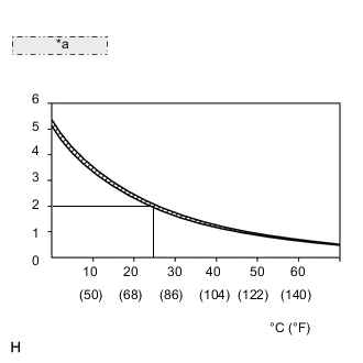
| *a | Resistance (kΩ) |
The battery temperature sensor built into the battery current sensor assembly detects battery temperature.
A thermistor is integrated into the battery temperature sensor, and the resistance in the battery temperature sensor changes according to the battery temperature.
The resistance of the thermistor in the battery temperature sensor decreases as the battery temperature increases. The resistance increases as the temperature decreases.
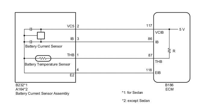
The battery temperature sensor is connected to the ECM. The ECM supplies 5 V from the THB terminal to the battery temperature sensor through resistor R.
The battery temperature sensor and resistor R are connected in series. This results in fluctuations in the voltage supplied from the THB terminal when the resistance changes according to the battery temperature.
The ECM determines the battery temperature according to fluctuations in voltage. When the battery temperature is high, the ECM determines to reduce the amount of current supplied from the generator in order to protect the battery.
| DTC No. | Detection Item | DTC Detection Condition | Trouble Area | Warning Indicate | Memory | Note |
|---|---|---|---|---|---|---|
| P0516 | Battery Temperature Sensor Circuit Low | Battery temperature sensor output value is less than 0.2 V for 0.5 seconds or more with the ignition switch ON (1 trip detection logic) |
|
Charge warning light does not come on | DTC stored | w/ Battery Current Sensor |
| P0517 | Battery Temperature Sensor Circuit High | Battery temperature sensor output value is higher than 4.8 V for 0.5 seconds or more with the ignition switch ON (1 trip detection logic) |
|
Charge warning light does not come on | DTC stored | w/ Battery Current Sensor |
WIRING DIAGRAM
CAUTION / NOTICE / HINT
Note
Before replacing the ECM, refer to Service Bulletin.
PROCEDURE
-
INSPECT BATTERY CURRENT SENSOR ASSEMBLY
-
Inspect the battery current sensor assembly.
Result Result Proceed to OK (for Sedan) A OK (except Sedan) B NG C
B 
CHECK HARNESS AND CONNECTOR (ECM - BATTERY CURRENT SENSOR ASSEMBLY) Click here
C 
REPLACE BATTERY CURRENT SENSOR ASSEMBLY Click here
A 
-
-
CHECK HARNESS AND CONNECTOR (ECM - BATTERY CURRENT SENSOR ASSEMBLY)
-
Disconnect the B186 ECM connector.
-
Disconnect the B232 battery current sensor assembly connector.
-
Measure the resistance according to the value(s) in the table below.
Standard Resistance (Check for Open) Tester Connection Condition Specified Condition B186-87 (THB) - B232-1 (THB) Always Below 1 Ω B186-118 (EIB) - B232-4 (E2) Always Below 1 Ω B186-117 (VCIB) - B232-2 (VC5) Always Below 1 Ω Standard Resistance (Check for Short) Tester Connection Condition Specified Condition B186-87 (THB) or B232-1 (THB) - Body ground Always 10 kΩ or higher B186-118 (EIB) or B232-4 (E2) - Body ground Always 10 kΩ or higher B186-117 (VCIB) or B232-2 (VC5) - Body ground Always 10 kΩ or higher Result Proceed to OK NG
OK
REPLACE ECM Click here
NG
REPAIR OR REPLACE HARNESS OR CONNECTOR
-
-
CHECK HARNESS AND CONNECTOR (ECM - BATTERY CURRENT SENSOR ASSEMBLY)
-
Disconnect the B186 ECM connector.
-
Disconnect the A164 battery current sensor assembly connector.
-
Measure the resistance according to the value(s) in the table below.
Standard Resistance (Check for Open) Tester Connection Condition Specified Condition B186-87 (THB) - A164-1 (THB) Always Below 1 Ω B186-118 (EIB) - A164-4 (E2) Always Below 1 Ω B186-117 (VCIB) - A164-2 (VC5) Always Below 1 Ω Standard Resistance (Check for Short) Tester Connection Condition Specified Condition B186-87 (THB) or A164-1 (THB) - Body ground Always 10 kΩ or higher B186-118 (EIB) or A164-4 (E2) - Body ground Always 10 kΩ or higher B186-117 (VCIB) or A164-2 (VC5) - Body ground Always 10 kΩ or higher Result Proceed to OK NG
OK
REPLACE ECM Click here
NG
REPAIR OR REPLACE HARNESS OR CONNECTOR
-