GENERATOR DISASSEMBLY

PROCEDURE
-
REMOVE GENERATOR PULLEY CAP
-

Remove the generator pulley cap from the generator pulley with clutch.
Note
Do not reuse the generator pulley cap.
-
-
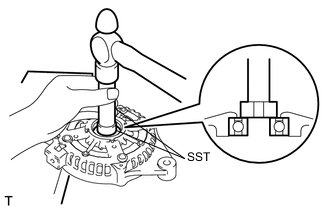
REMOVE GENERATOR PULLEY WITH CLUTCH
-
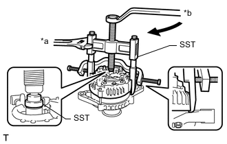
Secure the generator assembly in a vise between aluminum plates.
-

*a Rotor Shaft Fit the rotor shaft end into SST (A).
- SST
- 09820-30010
-
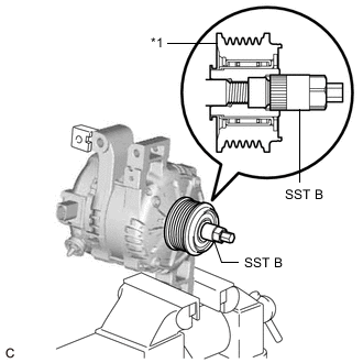
*1 Generator Pulley with Clutch Fit SST (B) to the generator pulley with clutch.
-
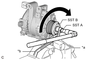
*a Turn *b Hold Loosen the generator pulley with clutch by turning SST (A) as shown in the illustration.
Note
-
Check that the generator assembly is secured in the vise tightly.
-
Hold SST tightly during the operation.
-
-
Remove SST (A) and (B) from the generator pulley with clutch.
-
Remove the generator pulley with clutch from the rotor shaft.
-
Remove the generator assembly from the vise.
-
-
REMOVE GENERATOR REAR END COVER
-
Place the generator assembly on the generator pulley with clutch.
-
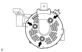
Remove the 3 bolts and generator rear end cover from the generator coil assembly.
-
-
REMOVE GENERATOR TERMINAL INSULATOR
-

Remove the generator terminal insulator from the generator coil assembly.
-
-
REMOVE GENERATOR BRUSH HOLDER ASSEMBLY
-
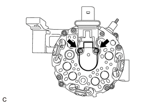
Remove the 2 screws and generator brush holder assembly from the generator coil assembly.
-
-
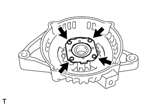
REMOVE GENERATOR COIL ASSEMBLY
-
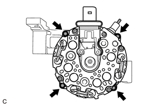
Remove the 4 bolts.
-
*a Hold *b Turn Using SST, remove the generator coil assembly.
- SST
- 09950-40011 ( 09951-04020, 09952-04010, 09953-04020, 09954-04010, 09955-04071, 09957-04010, 09958-04011 )
-
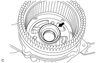
Remove the bearing cover packing.
Note
If the bearing cover packing breaks, remove the broken pieces completely.
Tech Tips
The bearing cover packing may be installed on the generator rotor assembly.
-
-
REMOVE GENERATOR ROTOR ASSEMBLY
-
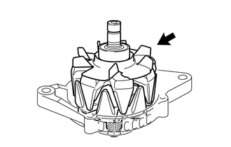
Remove the generator rotor assembly.
Note
Do not drop the generator rotor assembly.
-
-
INSPECT GENERATOR DRIVE END FRAME BEARING
-
REMOVE GENERATOR DRIVE END FRAME BEARING
-
Remove the 4 screws and retainer plate from the generator drive end frame.
-
Using SST and a hammer, tap out the generator drive end frame bearing.
- SST
- 09950-60010 ( 09951-00250 )
- 09950-70010 ( 09951-07100 )
-