ULTRASONIC SENSOR(for Sedan Front Side) REMOVAL
PROCEDURE
-
REMOVE FRONT BUMPER ASSEMBLY
-
REMOVE NO. 1 ULTRASONIC SENSOR
Tech Tips
-
These illustrations are for the LH side. The orientation for the RH side is the opposite of the LH side.
-
Use the same procedure for all No. 1 ultrasonic sensors.
-
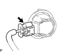
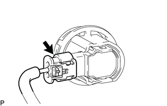
Disconnect the connector.
-
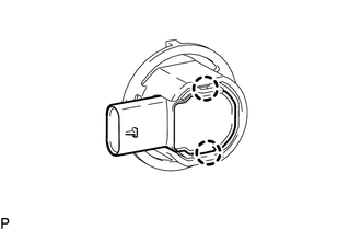
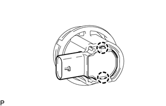
Disengage the 2 claws to remove the No. 1 ultrasonic sensor.
-
-
REMOVE ULTRASONIC SENSOR CLIP
-
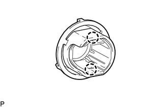
Disengage the 2 claws to remove the ultrasonic sensor clip.
Tech Tips
-
This illustration is for the LH side. The orientation for the RH side is the opposite of the LH side.
-
Use the same procedure for all ultrasonic sensor clips.
-
-
-
REMOVE NO. 1 ULTRASONIC SENSOR RETAINER
-
REMOVE NO. 2 ULTRASONIC SENSOR
Tech Tips
-
These illustrations are for the LH side. The orientation for the RH side is the opposite of the LH side.
-
Use the same procedure for all No. 2 ultrasonic sensors.
-
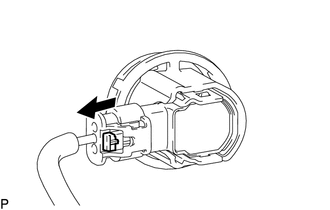
Using a screwdriver with its tip wrapped with protective tape, slide the connector lock as shown in the illustration.
-
Disconnect the connector.
-
Disengage the 2 claws to remove the No. 2 ultrasonic sensor.
-
-
REMOVE ULTRASONIC SENSOR CLIP
-
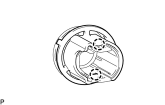
Disengage the 2 claws to remove the ultrasonic sensor clip.
Tech Tips
-
This illustration is for the LH side. The orientation for the RH side is the opposite of the LH side.
-
Use the same procedure for all ultrasonic sensor clips.
-
-
-
REMOVE NO. 2 ULTRASONIC SENSOR RETAINER