MONOLITHIC CONVERTER(w/ Glow Plug Controller) INSTALLATION
CAUTION / NOTICE / HINT
Tech Tips
After replacing the DPF catalytic converter, perform the "DPF Deterioration Record Clear" function using the GTS.
PROCEDURE
-
INSTALL NO. 2 EXHAUST GAS TEMPERATURE SENSOR
-
INSTALL NO. 1 VACUUM PIPE
-
Temporarily install the No. 1 vacuum pipe to the No. 2 exhaust manifold.
-
Connect the No. 1 vacuum pipe to the exhaust manifold with the bolt.
- Torque:
- 21 N*m { 214 kgf*cm, 15 ft.*lbf }
-
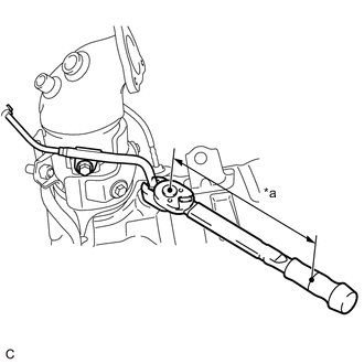
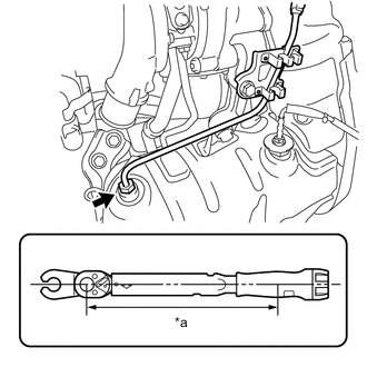
*a Torque Wrench Fulcrum Length Using a 14 mm union nut wrench, tighten the No. 1 vacuum pipe.
- Torque:
- Specified tightening torque
- 48 N*m { 489 kgf*cm, 35 ft.*lbf }
Tech Tips
-
Calculate the torque wrench reading when changing the fulcrum length of the torque wrench.
-
When using a 14 mm union nut wrench (fulcrum length of 25 mm (0.984 in.)) + torque wrench (fulcrum length of 180 mm (7.09 in.)): 42 N*m (428 kgf*cm, 31 ft.*lbf)
-
-
INSTALL NO. 2 EXHAUST MANIFOLD
-
Install a new outlet turbine elbow gasket to the turbocharger sub-assembly.
-
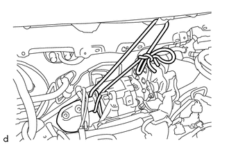
As shown in the illustration, secure the No. 2 exhaust manifold to the vehicle using a rope or similar.
Note
Make sure to perform this step in order to prevent the exhaust manifold from falling.
-
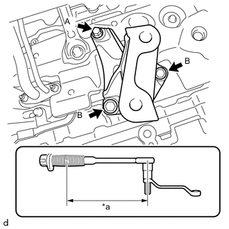
*a Torque Wrench Fulcrum Length Temporarily install the No. 1 manifold support bracket to the cylinder block sub-assembly with the 3 bolts.
-
Using a 12 x 14 mm offset wrench and a 12 mm hexagon socket wrench, tighten the bolt A.
- Torque:
- Specified tightening torque
- 37 N*m { 377 kgf*cm, 27 ft.*lbf }
Tech Tips
-
Calculate the torque wrench reading when changing the fulcrum length of the torque wrench.
-
When using a 12 x 14 mm offset wrench and a 12 mm hexagon socket wrench (fulcrum length of 206 mm (8.11 in.)) + torque wrench (fulcrum length of 180 mm (7.09 in.)): 17 N*m (173 kgf*cm, 13 ft.*lbf)
-
Tighten the 2 bolts B.
- Torque:
- 37 N*m { 377 kgf*cm, 27 ft.*lbf }
-
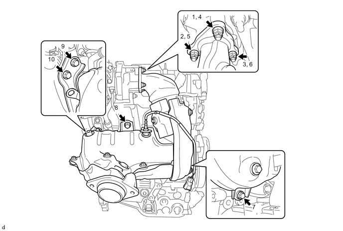
Temporarily install the No. 2 exhaust manifold to the turbocharger sub-assembly, No. 1 manifold support bracket, manifold stay and No. 2 manifold support bracket with the 4 bolts and 3 new nuts.
-
Tighten the 4 bolts and 3 nuts in the order shown in the illustration.
- Torque:
- Bolt
- 37 N*m { 377 kgf*cm, 27 ft.*lbf }
- Nut
- 26 N*m { 265 kgf*cm, 19 ft.*lbf }
-
-
INSTALL DRIVE SHAFT HEAT INSULATOR SUB-ASSEMBLY
-
Install the drive shaft heat insulator sub-assembly to the No. 1 manifold support bracket with the 2 nuts.
- Torque:
- 17.6 N*m { 179 kgf*cm, 13 ft.*lbf }
-
-
INSTALL NO. 4 MANIFOLD SUPPORT BRACKET
-
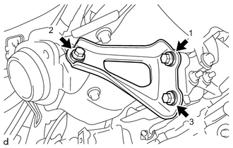
Install the No. 4 manifold support bracket to the No. 2 exhaust manifold and No. 1 manifold support bracket with the 3 bolts in the order shown in the illustration.
- Torque:
- 37 N*m { 377 kgf*cm, 27 ft.*lbf }
-
-
INSTALL FRONT SUSPENSION CROSSMEMBER SUB-ASSEMBLY
-
INSTALL NO. 5 MANIFOLD SUPPORT BRACKET
-
Install the No. 5 manifold support bracket to the No. 2 exhaust manifold and cylinder block sub-assembly with the 2 bolts in the order shown in the illustration.
- Torque:
- 37 N*m { 377 kgf*cm, 27 ft.*lbf }
-
-
INSTALL NO. 2 VACUUM PIPE
-
Temporarily install the No. 2 vacuum pipe to the No. 2 exhaust manifold.
-
Connect the No. 2 vacuum pipe to the manifold stay with the bolt.
- Torque:
- 21 N*m { 214 kgf*cm, 15 ft.*lbf }
-
*a Torque Wrench Fulcrum Length Using a 14 mm union nut wrench, tighten the No. 2 vacuum pipe.
- Torque:
- Specified tightening torque
- 30 N*m { 306 kgf*cm, 22 ft.*lbf }
Tech Tips
-
Calculate the torque wrench reading when changing the fulcrum length of the torque wrench.
-
When using a 14 mm union nut wrench (fulcrum length of 25 mm (0.984 in.)) + torque wrench (fulcrum length of 180 mm (7.09 in.)): 26 N*m (265 kgf*cm, 19 ft.*lbf)
-
Connect the wire harness to the No. 2 vacuum pipe.
-
-
INSTALL FRONT NO. 1 FLOOR HEAT INSULATOR
-
INSTALL FRONT EXHAUST PIPE ASSEMBLY
-
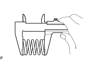
Using a vernier caliper, measure the free length of the compression springs.
Minimum Free Length (Front) 41.5 mm (1.63 in.) Minimum Free Length (Rear) 38.5 mm (1.52 in.) If the free length is less than the minimum, replace the compression spring.
-
Temporarily install 2 new gaskets to the front exhaust pipe assembly and No. 2 exhaust manifold.
-
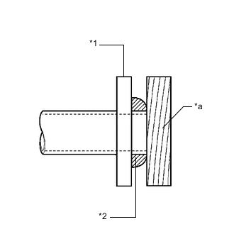
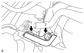
*1 Front Exhaust Pipe Assembly or No. 2 Exhaust Manifold *2 Gasket *a Wooden Block Using a plastic hammer and wooden block, tap in the 2 gaskets until each surface is flush with the front exhaust pipe assembly and No. 2 exhaust manifold.
Note
-
Be sure to install the gaskets in the correct direction.
-
Do not reuse the gaskets.
-
Do not damage the gaskets.
-
Do not push in the gaskets by using the exhaust pipes when connecting them.
-
-
Connect the front exhaust pipe assembly to the 2 exhaust pipe supports.
-
Install the front exhaust pipe assembly to the No. 2 exhaust manifold with the 2 bolts and 2 compression springs.
- Torque:
- 43 N*m { 438 kgf*cm, 32 ft.*lbf }
Tech Tips
After installation, check that the space between the flanges of the No. 2 exhaust manifold and front exhaust pipe assembly are consistent front-to-rear and left-to-right.
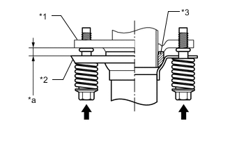
*1 No. 2 Exhaust Manifold *2 Front Exhaust Pipe Assembly *3 Gasket *a Space between Flanges: 8.5 mm (0.335 in.) -
Install the front exhaust pipe assembly to the center exhaust pipe assembly with the 2 compression springs and 2 bolts.
- Torque:
- 43 N*m { 438 kgf*cm, 32 ft.*lbf }
Tech Tips
After installation, check that the space between the flanges of the front exhaust pipe assembly and center exhaust pipe assembly are consistent front-to-rear and left-to-right.
*1 Front Exhaust Pipe Assembly *2 Center Exhaust Pipe Assembly *3 Gasket *a Space between Flanges: 6.5 mm (0.256 in.)
-
-
INSTALL FRONT CENTER FLOOR BRACE SUB-ASSEMBLY
-
INSTALL FRONT DRIVE SHAFT ASSEMBLY RH
-
INSTALL NO. 1 TURBO INSULATOR
-
Install the No. 1 turbo insulator to the turbocharger sub-assembly and No. 2 exhaust manifold with the 3 bolts.
- Torque:
- 7.0 N*m { 71 kgf*cm, 62 in.*lbf }
-
Connect the wire harness to the No. 1 turbo insulator.
-
-
INSTALL NO. 1 AIR TUBE
-
INSTALL AIR CLEANER CASE SUB-ASSEMBLY
-
INSTALL AIR CLEANER CAP SUB-ASSEMBLY
-
INSTALL BATTERY
-
INSTALL NO. 2 HOSE TO HOSE TUBE (for LHD)
-
Connect the No. 2 hose to hose tube to the vehicle body with the 2 nuts.
- Torque:
- 5.4 N*m { 55 kgf*cm, 48 in.*lbf }
-
Connect the check valve to connector tube hose to the No. 2 hose to hose tube and slide the clip to secure it.
-
-
INSTALL NO. 2 HOSE TO HOSE TUBE (for RHD)
-
Connect the No. 2 hose to hose tube to the vehicle body with the 2 nuts.
- Torque:
- 5.4 N*m { 55 kgf*cm, 48 in.*lbf }
-
-
INSTALL SENSOR BRACKET
-
Install the sensor bracket to the cylinder head cover sub-assembly with the 2 bolts.
- Torque:
- 11 N*m { 112 kgf*cm, 8 ft.*lbf }
-
-
INSTALL DIFFERENTIAL PRESSURE SENSOR
-
INSTALL EXHAUST GAS TEMPERATURE SENSOR
-
INSTALL AIR FUEL RATIO SENSOR
-
LEARNING DIFFERENTIAL PRESSURE SENSOR ASSEMBLY
-
CONNECT CABLE TO NEGATIVE BATTERY TERMINAL
Note
When disconnecting the cable, some systems need to be initialized after the cable is reconnected.
-
INSPECT FOR EXHAUST GAS LEAK