EXHAUST GAS TEMPERATURE SENSOR(w/ Glow Plug Controller) INSTALLATION
PROCEDURE
-
INSTALL NO. 2 EXHAUST GAS TEMPERATURE SENSOR
Note
If the No. 2 exhaust gas temperature sensor is dropped, replace it with a new one.
-
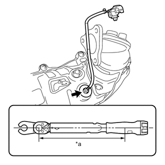
*a Torque Wrench Fulcrum Length Using a 14 mm union nut wrench, install the No. 2 exhaust gas temperature sensor to the No. 2 exhaust manifold.
- Torque:
- Specified tightening torque
- 30 N*m { 306 kgf*cm, 22 ft.*lbf }
Tech Tips
-
Calculate the torque wrench reading when changing the fulcrum length of the torque wrench.
-
When using a 14 mm union nut wrench (fulcrum length of 25 mm (0.984 in.)) + torque wrench (fulcrum length of 180 mm (7.09 in.)): 26 N*m (265 kgf*cm, 19 ft.*lbf)
-
-
INSTALL NO. 2 EXHAUST MANIFOLD
-
INSTALL DRIVE SHAFT HEAT INSULATOR SUB-ASSEMBLY
-
INSTALL NO. 4 MANIFOLD SUPPORT BRACKET
-
INSTALL FRONT SUSPENSION CROSSMEMBER SUB-ASSEMBLY
-
INSTALL NO. 5 MANIFOLD SUPPORT BRACKET
-
INSTALL FRONT NO. 1 FLOOR HEAT INSULATOR
-
INSTALL FRONT EXHAUST PIPE ASSEMBLY
-
INSTALL FRONT CENTER FLOOR BRACE SUB-ASSEMBLY
-
INSTALL FRONT DRIVE SHAFT ASSEMBLY RH
-
INSTALL NO. 1 TURBO INSULATOR
-
INSTALL NO. 1 AIR TUBE
-
INSTALL AIR CLEANER CASE SUB-ASSEMBLY
-
INSTALL AIR CLEANER CAP SUB-ASSEMBLY
-
INSTALL BATTERY
-
INSTALL NO. 2 HOSE TO HOSE TUBE (for LHD)
-
INSTALL NO. 2 HOSE TO HOSE TUBE (for RHD)
-
INSTALL NO. 2 ENGINE COVER BRACKET
-
INSTALL SENSOR BRACKET
-
INSTALL DIFFERENTIAL PRESSURE SENSOR ASSEMBLY
-
INSTALL EXHAUST GAS TEMPERATURE SENSOR
Note
If the exhaust gas temperature sensor is dropped, replace it with a new one.
-
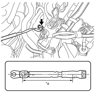
*a Torque Wrench Fulcrum Length Using a 14 mm union nut wrench, install the exhaust gas temperature sensor to the No. 2 exhaust manifold.
- Torque:
- Specified tightening torque
- 30 N*m { 306 kgf*cm, 22 ft.*lbf }
Tech Tips
-
Calculate the torque wrench reading when changing the fulcrum length of the torque wrench.
-
When using a 14 mm union nut wrench (fulcrum length of 25 mm (0.984 in.)) + torque wrench (fulcrum length of 180 mm (7.09 in.)): 26 N*m (265 kgf*cm, 19 ft.*lbf)
-
Engage the clamp to connect the wire harness to the wire harness clamp bracket.
-
Engage the claw to connect the exhaust gas temperature sensor connector to the wire harness clamp bracket.
-
Install the wire harness clamp bracket to the timing chain cover assembly with the bolt.
- Torque:
- 9.0 N*m { 92 kgf*cm, 80 in.*lbf }
-
Connect the exhaust gas temperature sensor connector.
-
-
INSTALL WIRE HARNESS CLAMP BRACKET
-
INSTALL NO. 1 WIRE HARNESS HEAT INSULATOR
-
INSTALL OUTER COWL TOP PANEL
-
for LHD:
-
for RHD:
-
-
INSTALL NO. 2 HEATER AIR DUCT SPLASH SHIELD SEAL
-
for LHD:
-
for RHD:
-
-
INSTALL WATER GUARD PLATE LH
-
for LHD:
-
for RHD:
-
-
INSTALL WINDSHIELD WIPER MOTOR AND LINK ASSEMBLY
-
INSTALL NO. 1 ENGINE COVER (w/ No. 1 Engine Cover)
-
LEARNING DIFFERENTIAL PRESSURE SENSOR ASSEMBLY
-
CONNECT CABLE TO NEGATIVE BATTERY TERMINAL
Note
When disconnecting the cable, some systems need to be initialized after the cable is reconnected.
-
INSPECT FOR EXHAUST GAS LEAK