MONOLITHIC CONVERTER(w/o Glow Plug Controller) INSTALLATION
CAUTION / NOTICE / HINT
Tech Tips
After replacing the DPF catalytic converter, perform the "DPF Deterioration Record Clear" function using the GTS.
PROCEDURE
-
INSTALL EXHAUST GAS TEMPERATURE SENSOR
-
INSTALL NO. 2 EXHAUST GAS TEMPERATURE SENSOR
-
INSTALL EXHAUST MANIFOLD CONVERTER SUB-ASSEMBLY
-
Install a new gasket to the turbocharger.
-
Temporarily install the exhaust manifold converter sub-assembly with 3 new nuts and a new bolt.
-
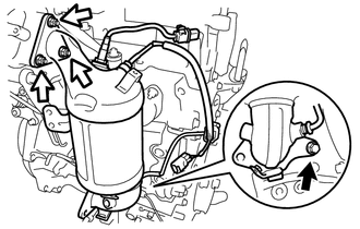

Bolt 
Nut Fully tighten the 3 nuts first, and then tighten the bolt.
- Torque:
- Nut
- 26 N*m { 265 kgf*cm, 19 ft.*lbf }
- Bolt
- 37 N*m { 377 kgf*cm, 27 ft.*lbf }
-
Install the wire harness bracket with the bolt.
- Torque:
- 8.0 N*m { 82 kgf*cm, 71 in.*lbf }
-
Install the exhaust gas temperature sensor connector and No. 2 exhaust gas temperature sensor connector to the wire harness bracket.
-
Engage the 2 wire harness clamps with the wire harness bracket and cylinder block side cover.
-
Connect the exhaust gas temperature sensor connector and No. 2 exhaust gas temperature sensor connector.
-
Install the harness bracket with the bolt.
- Torque:
- 8.0 N*m { 82 kgf*cm, 71 in.*lbf }
-
Engage the 2 wire harness clamps to the wire harness bracket.
-
-
INSTALL NO. 1 VACUUM PIPE
-
Temporarily install the No. 1 vacuum pipe with the bolt and No. 1 vacuum pipe to the exhaust manifold converter sub-assembly.
-
Using a 14 mm union nut wrench, install the No. 1 vacuum pipe.
- Torque:
- 48 N*m { 489 kgf*cm, 35 ft.*lbf }
Note
Use the formula to calculate special torque values for situations where a union nut wrench is combined with a torque wrench.
-
Fully tighten the bolt.
- Torque:
- 21 N*m { 214 kgf*cm, 15 ft.*lbf }
-
-
INSTALL NO. 2 EXHAUST MANIFOLD CONVERTER SUB-ASSEMBLY
-
Install a new gasket to the exhaust manifold converter sub-assembly.
-
Temporarily install the No. 2 exhaust manifold converter sub-assembly with the 2 nuts.
-
Temporarily install the No. 3 manifold support bracket to the No. 2 exhaust manifold converter sub-assembly and No. 2 manifold support bracket with the 3 bolts.
-
Temporarily install the No. 4 manifold support bracket to the No. 2 exhaust manifold converter sub-assembly and manifold support bracket with the 3 bolts.
-
Tighten the 2 nuts.
- Torque:
- 37 N*m { 377 kgf*cm, 27 ft.*lbf }
-
-
INSTALL NO. 3 MANIFOLD SUPPORT BRACKET
-
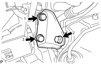
Fully tighten the 3 bolts in the order shown in the illustration.
- Torque:
- 37 N*m { 377 kgf*cm, 27 ft.*lbf }
-
-
INSTALL NO. 4 MANIFOLD SUPPORT BRACKET
-
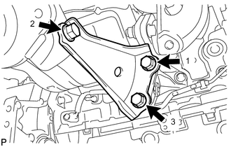
Fully tighten the 3 bolts in the order shown in the illustration.
- Torque:
- 37 N*m { 377 kgf*cm, 27 ft.*lbf }
-
-
INSTALL DRIVE SHAFT HEAT INSULATOR SUB-ASSEMBLY
-
Install the drive shaft heat insulator sub-assembly with the 2 nuts.
- Torque:
- 17.6 N*m { 179 kgf*cm, 13 ft.*lbf }
-
-
INSTALL NO. 2 VACUUM PIPE
-
Temporarily install the No. 2 vacuum pipe with the 2 bolts.
-
Using a 14 mm union nut wrench, install the No. 2 vacuum pipe.
- Torque:
- 30 N*m { 306 kgf*cm, 22 ft.*lbf }
Note
Use the formula to calculate special torque values for situations where a union nut wrench is combined with a torque wrench.
-
Fully tighten the 2 bolts.
- Torque:
- 20 N*m { 204 kgf*cm, 15 ft.*lbf }
-
-
INSTALL VACUUM TRANSMITTING HOSE ASSEMBLY
-
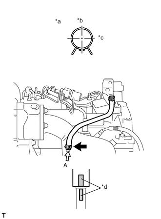
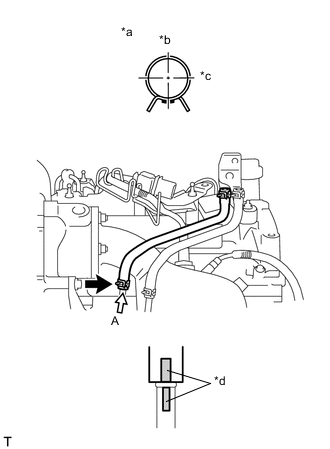
*a View A *b Front of Vehicle *c RH Side *d Paint Mark Install the vacuum transmitting hose assembly to the No. 1 vacuum pipe and slide the clip to secure it.
Note
Connect the vacuum transmitting hose assembly so that the paint mark of the vacuum transmitting hose assembly is as shown in the illustration.
-
-
INSTALL NO. 2 VACUUM TRANSMITTING HOSE ASSEMBLY
-
*a View A *b Front of Vehicle *c RH Side *d Paint Mark Install the No. 2 vacuum transmitting hose assembly to the No. 2 vacuum pipe and slide the clip to secure it.
Note
Connect the No. 2 vacuum transmitting hose assembly so that the paint mark of the No. 2 vacuum transmitting hose assembly is as shown in the illustration.
-
-
INSTALL AIR FUEL RATIO SENSOR
-
INSTALL NO. 1 TURBO INSULATOR
-
Install the No. 1 turbo insulator with the 3 bolts.
- Torque:
- 7.0 N*m { 71 kgf*cm, 62 in.*lbf }
-
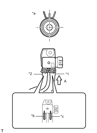
*1 Vacuum Transmitting Hose Assembly *2 No. 2 Vacuum Transmitting Hose Assembly *a View A *b Paint Mark (Yellow) *c Paint Mark (Pink) Connect the vacuum transmitting hose and No. 2 vacuum transmitting hose to the differential pressure sensor assembly, and slide the 2 clips to secure them.
Note
Connect the vacuum transmitting hose assembly and No. 2 vacuum transmitting hose assembly so that the paint marks of the vacuum transmitting hose assembly and No. 2 vacuum transmitting hose assembly are as shown in the illustration.
-
-
INSTALL HARNESS BRACKET
-
INSTALL FRONT NO. 1 FLOOR HEAT INSULATOR
-
INSTALL FRONT EXHAUST PIPE ASSEMBLY
-
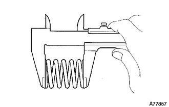
Using a vernier caliper, measure the free length of the compression springs.
Minimum (Front) 41.5 mm (1.63 in.) Minimum (Rear) 38.5 mm (1.52 in.) If the free length is less than the minimum, replace the compression spring.
-
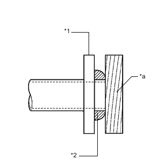
*1 Front Exhaust Pipe Assembly or No. 2 Exhaust Manifold Converter Sub-assembly *2 Gasket *a Wooden Block Using a plastic hammer and wooden block, tap in 2 new gaskets until each surface is flush with the front exhaust pipe assembly and No. 2 exhaust manifold converter sub-assembly.
Note
-
Be sure to install the gaskets in the correct direction.
-
Do not reuse the gaskets.
-
Do not damage the gaskets.
-
Do not push in the gaskets by using the exhaust pipes when connecting them.
-
-
Connect the front exhaust pipe assembly to the 2 exhaust pipe supports.
-
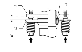
*1 No. 2 Exhaust Manifold Converter Sub-assembly *2 Front Exhaust Pipe Assembly *3 Gasket *a Space Between Flanges: 8.5 mm (0.335 in.) Install the front exhaust pipe assembly to the No. 2 exhaust manifold converter sub-assembly with the 2 bolts and 2 compression springs.
- Torque:
- 43 N*m { 438 kgf*cm, 32 ft.*lbf }
Tech Tips
After installation, check that the space between the flanges of the No. 2 exhaust manifold converter sub-assembly and front exhaust pipe assembly are consistent front-to-rear and left-to-right.
-
*1 Front Exhaust Pipe Assembly *2 Center Exhaust Pipe Assembly *3 Gasket *a Space Between Flanges: 6.5 mm (0.256 in.) Install the front exhaust pipe assembly to the center exhaust pipe assembly with the 2 compression springs and 2 bolts.
- Torque:
- 43 N*m { 438 kgf*cm, 32 ft.*lbf }
Tech Tips
After installation, check that the space between the flanges of the front exhaust pipe assembly and center exhaust pipe assembly are consistent front-to-rear and left-to-right.
-
-
INSTALL FRONT CENTER FLOOR BRACE SUB-ASSEMBLY
-
INSTALL NO. 1 AIR TUBE
-
INSTALL AIR CLEANER CASE SUB-ASSEMBLY
-
INSTALL AIR CLEANER CAP SUB-ASSEMBLY
-
INSTALL BATTERY
-
INSTALL OUTER COWL TOP PANEL (for LHD)
-
for Sedan:
-
for Hatchback, Wagon:
-
-
INSTALL OUTER COWL TOP PANEL (for RHD)
-
for Sedan:
-
for Hatchback, Wagon:
-
-
INSTALL NO. 2 HEATER AIR DUCT SPLASH SHIELD SEAL (for LHD)
-
for Sedan:
-
for Hatchback, Wagon:
-
-
INSTALL NO. 2 HEATER AIR DUCT SPLASH SHIELD SEAL (for RHD)
-
for Sedan:
-
for Hatchback, Wagon:
-
-
INSTALL WATER GUARD PLATE LH (for LHD)
-
for Sedan:
-
for Hatchback, Wagon:
-
-
INSTALL WATER GUARD PLATE LH (for RHD)
-
for Sedan:
-
for Hatchback, Wagon:
-
-
INSTALL WINDSHIELD WIPER MOTOR AND LINK ASSEMBLY
-
CONNECT CABLE TO NEGATIVE BATTERY TERMINAL
Note
When disconnecting the cable, some systems need to be initialized after the cable is reconnected
-
INSPECT FOR EXHAUST GAS LEAK
-
INSTALL NO. 1 ENGINE COVER (w/ No. 1 Engine Cover)