MONOLITHIC CONVERTER INSTALLATION
CAUTION / NOTICE / HINT
Tech Tips
After replacing the DPF catalytic converter, perform the "DPF Deterioration Record Clear" function using the GTS.
PROCEDURE
-
INSTALL NO. 2 MANIFOLD CONVERTER INSULATOR
-
Install the No. 2 manifold converter insulator to the exhaust manifold converter sub-assembly with the 3 bolts.
- Torque:
- 28.5 N*m { 291 kgf*cm, 21 ft.*lbf }
-
-
INSTALL NO. 2 VACUUM PIPE
-
Temporarily install the No. 2 vacuum pipe to the exhaust manifold converter sub-assembly with the union nut and bolt.
-
Tighten the bolt.
- Torque:
- 25 N*m { 255 kgf*cm, 18 ft.*lbf }
-
Using a 14 mm union nut wrench, tighten the union nut.
- Torque:
- 30 N*m { 306 kgf*cm, 22 ft.*lbf }
Note
Use the formula to calculate special torque values for situations where a union nut wrench is combined with a torque wrench.
-
-
INSTALL NO. 1 VACUUM PIPE
-
Temporarily install the No. 1 vacuum pipe to the exhaust manifold converter sub-assembly with the union nut and bolt.
-
Tighten the bolt.
- Torque:
- 25 N*m { 255 kgf*cm, 18 ft.*lbf }
-
Using a 17 mm union nut wrench, tighten the union nut.
- Torque:
- 48 N*m { 489 kgf*cm, 35 ft.*lbf }
Note
Use the formula to calculate special torque values for situations where a union nut wrench is combined with a torque wrench.
-
-
INSTALL NO. 2 EXHAUST GAS TEMPERATURE SENSOR
-
INSTALL NO. 3 EXHAUST GAS TEMPERATURE SENSOR
-
INSTALL EXHAUST GAS TEMPERATURE SENSOR
-
INSTALL NO. 2 VACUUM TRANSMITTING HOSE ASSEMBLY
-
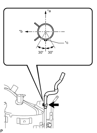
*a Front of the Vehicle *b LH Side *c Paint Mark (Pink) Install the No. 2 vacuum transmitting hose assembly to the No. 2 vacuum pipe and slide the clip to secure it.
Note
Connect the No. 2 vacuum transmitting hose assembly so that the paint mark of the No. 2 vacuum transmitting hose assembly is within the area shown in the illustration.
-
-
INSTALL VACUUM TRANSMITTING HOSE ASSEMBLY
-
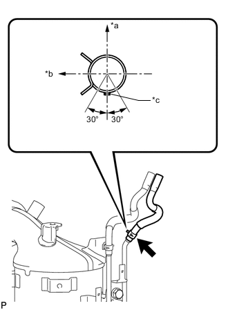
*a Front of the Vehicle *b LH Side *c Paint Mark (White) Install the vacuum transmitting hose assembly to the No. 1 vacuum pipe and slide the clip to secure it.
Note
Connect the vacuum transmitting hose assembly so that the paint mark of the vacuum transmitting hose assembly is within the area shown in the illustration.
-
-
INSTALL EXHAUST MANIFOLD CONVERTER SUB-ASSEMBLY
-
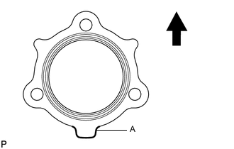

Top Install a new gasket to the turbocharger sub-assembly.
Tech Tips
Make sure that the part (A) is facing downwards as shown in the illustration.
-
Temporarily install the exhaust manifold converter sub-assembly with 3 new nuts.
-
Temporarily install the No. 2 exhaust manifold stay with the 2 bolts and nut.
-
Temporarily install the No. 2 manifold stay with the 3 bolts.
-
Temporarily install the manifold stay with the bolt and nut.
-
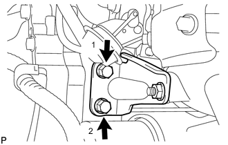
Tighten the 2 bolts of the No. 2 exhaust manifold stay in the order shown in the illustration.
- Torque:
- 56 N*m { 571 kgf*cm, 41 ft.*lbf }
-
Tighten the 3 nuts of the exhaust manifold converter sub-assembly.
- Torque:
- 25 N*m { 255 kgf*cm, 18 ft.*lbf }
Note
Tighten the nuts while pressing the exhaust manifold converter sub-assembly against the engine.
-
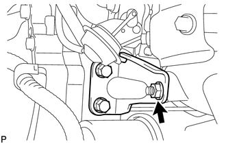
Tighten the nut of the No. 2 exhaust manifold stay.
- Torque:
- 56 N*m { 571 kgf*cm, 41 ft.*lbf }
-
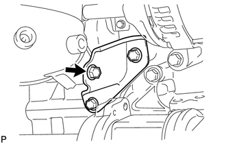
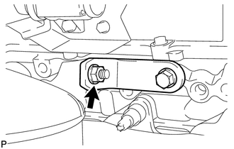
Tighten the bolt of the No. 2 manifold stay shown in the illustration.
- Torque:
- 56 N*m { 571 kgf*cm, 41 ft.*lbf }
Note
Tighten the bolt while pressing the No. 2 manifold stay against the exhaust manifold converter sub-assembly and cylinder block.
-
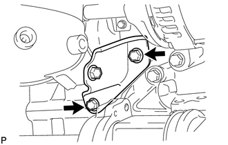
Tighten the 2 bolts of the No. 2 manifold stay shown in the illustration.
- Torque:
- 56 N*m { 571 kgf*cm, 41 ft.*lbf }
-
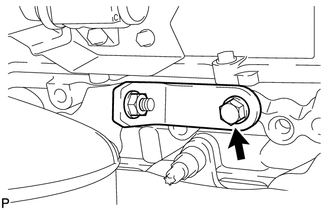
Tighten the bolt of the manifold stay.
- Torque:
- 25 N*m { 255 kgf*cm, 18 ft.*lbf }
Note
Tighten the bolt while pressing the manifold stay against the exhaust manifold converter sub-assembly and cylinder block.
-
Tighten the nut of the manifold stay.
- Torque:
- 25 N*m { 255 kgf*cm, 18 ft.*lbf }
-
Connect the 2 connectors.
-
-
INSTALL MANIFOLD CONVERTER INSULATOR SUB-ASSEMBLY
-
Install the manifold converter insulator sub-assembly to the exhaust manifold converter sub-assembly with the bolt.
- Torque:
- 28.5 N*m { 291 kgf*cm, 21 ft.*lbf }
Note
Make sure that the ceramic wool inside the manifold converter insulator sub-assembly does not fall out and is laid flat.
-
-
INSTALL NO. 4 MANIFOLD CONVERTER INSULATOR
-
Install the No. 4 manifold converter insulator to the exhaust manifold converter sub-assembly with the 4 bolts.
- Torque:
- 28.5 N*m { 291 kgf*cm, 21 ft.*lbf }
-
-
INSTALL ENGINE ASSEMBLY
-
PERFORM CATALYST RECORD OF DPF THERMAL DETERIORATION CLEAR FUNCTION