FUEL PUMP INSTALLATION

PROCEDURE
-
INSTALL FUEL SUCTION TUBE WITH PUMP AND GAUGE ASSEMBLY
-
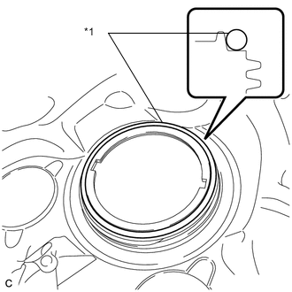
*1 Fuel Suction Tube Set Gasket Install a new fuel suction tube set gasket onto the fuel tank assembly.
-
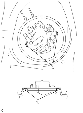
*a Notch *b Protrusion Set the fuel suction tube with pump and gauge assembly to the fuel tank assembly.
Note
Make sure that the fuel sender gauge arm does not bend.
-
Align the protrusions of the fuel suction tube with pump and gauge assembly with the notches of the fuel tank assembly.
-
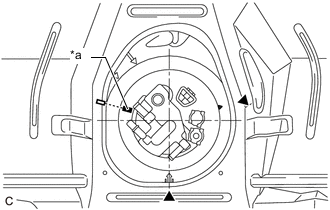
*a Paint Mark Place a paint mark on the fuel suction tube with pump and gauge assembly as shown in the illustration.
Tech Tips
Perform this step only when replacing the fuel suction tube with pump and gauge assembly.
-
-
INSTALL FUEL PUMP GAUGE RETAINER
-
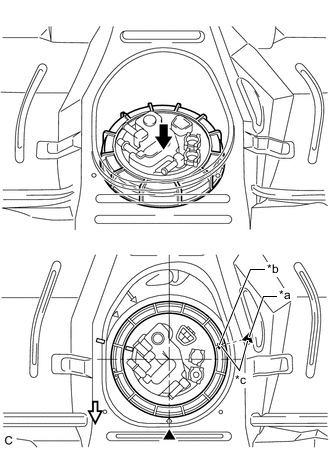
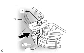
*a Copy of Start of Threads Mark *b Start of Threads of the Fuel Pump Gauge Retainer *c Align 
Press down 
Front Align the start of the threads of a new fuel pump gauge retainer with the start of threads mark that was copied onto the vehicle body and while pushing down the fuel suction tube with pump and gauge assembly, attach the fuel pump gauge retainer.
-
Install SST to the fuel pump gauge retainer.
-
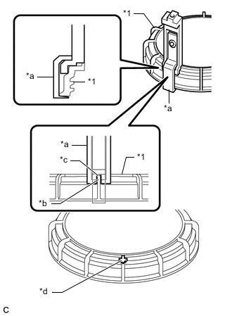
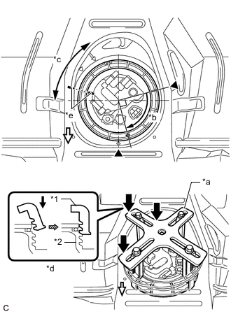
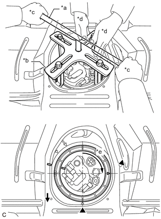
*1 Fuel Pump Gauge Retainer *a SST (Claw Set) *b Protrusion *c Notch *d Do not install SST (Claw Set) Set 4 SST (claw set) to the fuel pump gauge retainer.
- SST
- 09808-14031 ( 09808-01080, 09808-01090, 09808-01100 )
Note
-
Align the notch of SST (claw set) with the protrusion of the fuel pump gauge retainer.
-
Do not install SST (claw set) to the start of threads location of the fuel pump gauge retainer.
-
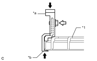
*1 Fuel Pump Gauge Retainer *a SST (Claw Set) *b Hook Push SST (Bolt) Push SST (claw set) against the fuel pump gauge retainer and tighten SST (bolt).
-
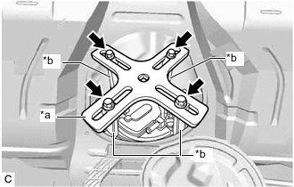
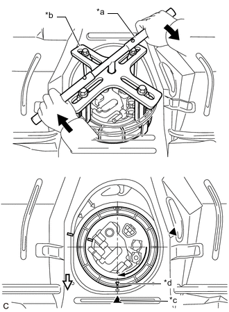
*a SST (Plate) *b SST (Claw Set) SST (Bolt) Temporarily install SST (plate) to SST (claw set) with 4 SST (bolt).
- SST
- 09808-14031 ( 09808-01030, 09808-01090 )
-
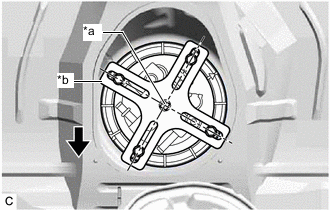
*a Center Point of Fuel Pump Gauge Retainer *b SST (Plate) Front Adjust the position of SST (claw set) so that the hole in SST (plate) for installing SST (handle) is in the center of the fuel pump gauge retainer.
-
*1 Fuel Pump Gauge Retainer *a SST (Plate) *b SST (Claw Set) *c SST (Bolt) Press Press SST (claw set) against the rib of the fuel pump gauge retainer and tighten SST (bolt).
-
-
*1 Fuel Pump Gauge Retainer *2 Fuel Tank Assembly *a SST (Plate) *b Tighten approximately 90° *c Fuel pump gauge retainer rises up *d Cross Section *e Paint Mark Press quickly and firmly Front While pressing down on the fuel suction tube with pump and gauge assembly, have another person firmly press the fuel pump gauge retainer against the threads of the fuel tank assembly, and tighten the fuel pump gauge retainer by approximately 90°.
Note
-
To prevent damage to parts, do not turn SST too vigorously.
-
Do not turn the fuel pump gauge retainer if the paint marks become misaligned.
-
-
Quickly and firmly press down on the part of the fuel pump gauge retainer closest to the rear of the vehicle to keep it from rising up.
Tech Tips
-
If the fuel pump gauge retainer cannot be properly pressed down due to the position of SST, set SST in a different position.
-
When fully pressing down the fuel pump gauge retainer, there will be a sound or tactile sensation of parts contacting each other, and at this point the fuel suction tube with pump and gauge assembly will stop rising up.
-
-
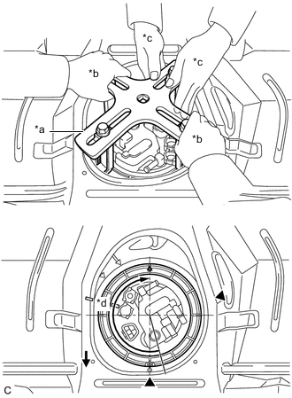
*a SST (Plate) *b One Person in Charge of Tightening *c One Person in Charge of Pressing Down *d Approximately 180° Front While pressing down on the fuel suction tube with pump and gauge assembly, have another person slowly tighten the fuel pump gauge retainer by approximately 180°.
-
Check the tightening status of the fuel pump gauge retainer.
-
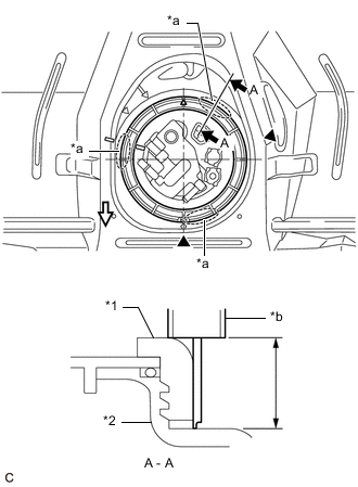
*1 Fuel Pump Gauge Retainer *2 Fuel Tank Assembly *a Measurement Position *b Vernier Caliper Front Using a vernier caliper, measure the distance from the fuel tank assembly to the upper surface of the fuel pump gauge retainer at 3 positions as shown in the illustration.
Standard Difference between the 3 measured values is 3 mm (0.118 in.) or less. Note
If the difference between measurements is approximately 6 mm (0.236 in.), the threads are cross-threaded by 1 row (6 mm (0.236 in.)), so remove and reinstall the fuel pump gauge retainer.
-
-
*a SST (Handle) *b SST (Plate) *c One Person in Charge of Tightening *d One Person in Charge of Pressing Down *e Approximately 90° Front Install SST (handle) to SST (plate).
- SST
- 09808-14031 ( 09808-01010, 09808-01020 )
-
While pressing down on the fuel suction tube with pump and gauge assembly, have another person use SST (handle) to slowly tighten the fuel pump gauge retainer approximately 90°.
-
*a SST (Handle) *b SST (Plate) *c Copy of Fully Tightened Mark *d Start of Threads of the Fuel Pump Gauge Retainer Tighten Front Slowly tighten the fuel pump gauge retainer until it reaches the fully tightened mark that was copied onto the vehicle body.
-
-
CONNECT FUEL TANK MAIN TUBE SUB-ASSEMBLY
-
Push the fuel tube joint onto the plug of the fuel suction plate sub-assembly, then install the tube joint clip.
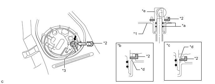
*1 Fuel Suction Plate Sub-assembly *2 Tube Joint Clip *3 Fuel Tank Main Tube Sub-assembly - - *a O-ring *b Correct *c Incorrect *d Collar *e Fuel Tube Joint - - Insert Insert Note
-
Check that there are no scratches or foreign matter around the connecting parts of the fuel tube joint and plug before performing this work.
-
Check that the fuel tube joint is securely inserted to the end.
-
Check that the tube joint clip is on the collar of the fuel tube joint as shown in the illustration.
-
After installing the tube joint clip, check that the fuel tank main tube sub-assembly is securely connected by pulling on it.
-
-
-
CHECK AIRTIGHTNESS
-
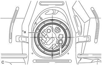
*a Soapy Water Application Area Apply soapy water to the contact areas between the fuel suction tube with pump and gauge assembly and fuel pump gauge retainer.
Note
Cover the connector of the fuel suction tube with pump and gauge assembly with protective tape.
-
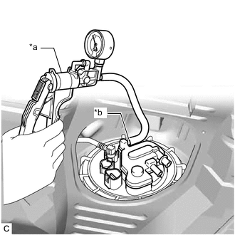
*a Vacuum Pump *b Port (A) Install a vacuum pump to the port (A) of the fuel suction tube with pump and gauge assembly as shown in the illustration.
-
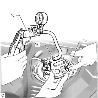
*a Port (A) *b Port (B) *c Port (C) *d Vacuum Pump Close the port (B) and port (C), and use the vacuum pump to apply 5 kPa (0.1 kgf/cm2, 0.7 psi) of compressed air to the port (A) as shown in the illustration.
Note
Do not apply more compressed air than necessary.
-
Check that the contact areas between the fuel suction tube with pump and gauge assembly and fuel pump gauge retainer are airtight.
Note
-
If air bubbles appear, remove and reinstall the fuel pump gauge retainer.
-
After a fuel pump gauge retainer and fuel suction tube set gasket have been used once, replace them with new parts.
-
When removing and reinstalling the fuel pump gauge retainer, make sure to clean away the soapy water to prevent the fuel suction tube set gasket from slipping out of position and being assembled incorrectly.
-
-
-
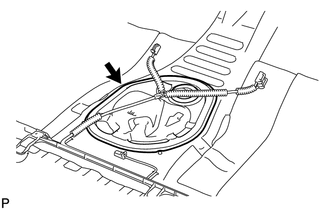
CONNECT NO. 2 FUEL TANK EVAPORATION TUBE
-
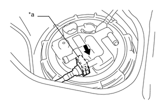
*a Retainer Connect the No. 2 fuel tank evaporation tube to the fuel suction tube with pump and gauge assembly.
-
-
CONNECT NO. 1 CHARCOAL CANISTER OUTLET HOSE
-
Connect the No. 1 charcoal canister outlet hose to the fuel suction tube with pump and gauge assembly.
Tech Tips
After connecting the No. 2 fuel tank evaporation tube and No. 1 charcoal canister outlet hose, check that the No. 2 fuel tank evaporation tube is positioned below the No. 1 charcoal canister outlet hose.
-
-
CONNECT NO. 1 FUEL EVAPORATION TUBE SUB-ASSEMBLY
-
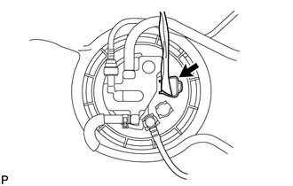
Connect the No. 1 fuel evaporation tube sub-assembly to the fuel suction tube with pump and gauge assembly and slide the clip to secure it.
-
-
CONNECT CABLE TO NEGATIVE BATTERY TERMINAL
Note
When disconnecting the cable, some systems need to be initialized after the cable is reconnected.
-
INSPECT FOR FUEL LEAK
-
INSTALL REAR FLOOR SERVICE HOLE COVER
-
Connect the fuel pump connector.
-
Install the rear floor service hole cover with new butyl tape.
-
Connect the 2 connectors.
-
-
INSTALL REAR SEAT CUSHION ASSEMBLY