FUEL INJECTOR INSTALLATION

PROCEDURE
-
INSTALL FUEL INJECTOR ASSEMBLY
-
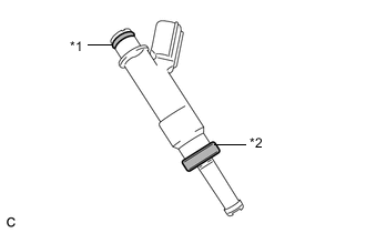
*1 O-ring *2 Injector Vibration Insulator Apply a light coat of gasoline or spindle oil to new injector vibration insulators and O-rings, and then install one onto each fuel injector assembly.
-
Apply a light coat of gasoline or spindle oil where the fuel delivery pipe sub-assembly contacts each O-ring.
-
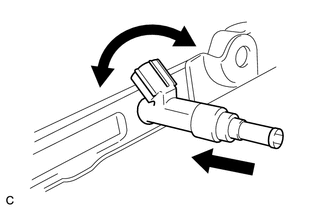
While turning the fuel injector assembly left and right, install it onto the fuel delivery pipe sub-assembly.
Note
-
Do not damage the fuel injector assembly or O-ring.
-
Do not twist the O-ring.
-
After installing each fuel injector assembly, check that it turns smoothly. If not, replace the O-ring with a new one.
-
-
-
INSTALL NO. 1 DELIVERY PIPE SPACER
-
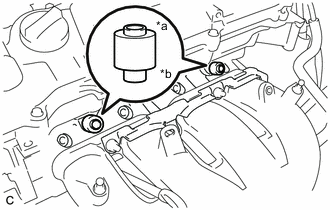
*a Fuel Delivery Pipe Sub-assembly Side *b Cylinder Head Side Install the 2 No. 1 delivery pipe spacers onto the cylinder head.
Note
Install the No. 1 delivery pipe spacers in the correct direction.
-
-
INSTALL FUEL DELIVERY PIPE SUB-ASSEMBLY
-
Install the fuel delivery pipe sub-assembly with fuel injector assemblies with the 2 bolts.
- Torque:
- 21 N*m { 214 kgf*cm, 15 ft.*lbf }
Note
-
Do not drop the fuel injector assemblies when installing the fuel delivery pipe sub-assembly.
-
After installing the fuel delivery pipe sub-assembly, check that the fuel injector assemblies turn smoothly.
-
Install the fuel delivery pipe sub-assembly to the cylinder head sub-assembly with the bolt.
- Torque:
- 21 N*m { 214 kgf*cm, 15 ft.*lbf }
-
Install the wire harness bracket to the intake manifold with the engine cover joint.
- Torque:
- 10 N*m { 102 kgf*cm, 7 ft.*lbf }
-
-
CONNECT FUEL TUBE SUB-ASSEMBLY
-
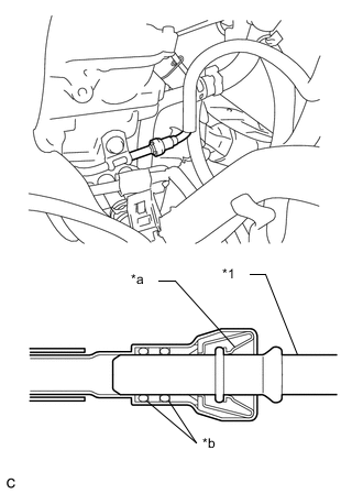
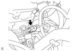
*1 Fuel Delivery Pipe Sub-assembly *a Retainer *b O-ring Connect the fuel tube sub-assembly connector to the fuel delivery pipe sub-assembly until a "click" sound is heard.
Note
-
Check that there are no scratches or foreign matter on the contact surfaces of the fuel tube sub-assembly connector and fuel delivery pipe sub-assembly before performing this work.
-
After connecting the fuel lines, check that the fuel tube sub-assembly connector and fuel delivery pipe sub-assembly are securely connected by pulling on them.
-
-
Type A:
-
Install a new No. 2 fuel pipe clamp.
-
-
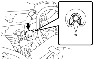
*a Claw Type B:
-
Install a new No. 2 fuel pipe clamp.
-
-
-
CONNECT ENGINE WIRE
-
Install the 2 wire harness brackets to the cylinder head sub-assembly with the 2 bolts.
- Torque:
- 12.5 N*m { 127 kgf*cm, 9 ft.*lbf }
-
Engage the 4 wire harness clamps to the wire harness bracket.
-
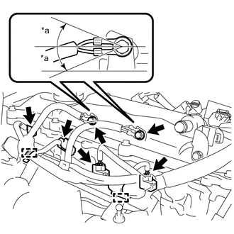
*a 20° Engage the 2 wire harness clamps.
-
Connect the 4 fuel injector assembly connectors.
-
Connect the ground wire to the cylinder head cover sub-assembly with the 2 bolts.
- Torque:
- 8.5 N*m { 87 kgf*cm, 75 in.*lbf }
Tech Tips
It is acceptable for the ground wires to be tilted +20° to -20°.
-
-
INSTALL AIR CLEANER CASE SUB-ASSEMBLY
-
INSTALL AIR CLEANER CAP SUB-ASSEMBLY
-
CONNECT CABLE TO NEGATIVE BATTERY TERMINAL
Note
When disconnecting the cable, some systems need to be initialized after the cable is reconnected.
-
INSPECT FOR FUEL LEAK
-
INSTALL NO. 2 CYLINDER HEAD COVER