FUEL INJECTOR REMOVAL

CAUTION / NOTICE / HINT
PROCEDURE
-
PRECAUTION
Note
After turning the ignition switch off, waiting time may be required before disconnecting the cable from the negative (-) battery terminal. Therefore, make sure to read the disconnecting the cable from the negative (-) battery terminal notice before proceeding with work.
-
DISCHARGE FUEL SYSTEM PRESSURE
-
DISCONNECT CABLE FROM NEGATIVE BATTERY TERMINAL
Note
When disconnecting the cable, some systems need to be initialized after the cable is reconnected.
-
REMOVE NO. 2 CYLINDER HEAD COVER
-
REMOVE AIR CLEANER CAP SUB-ASSEMBLY
-
REMOVE AIR CLEANER CASE SUB-ASSEMBLY
-
DISCONNECT ENGINE WIRE
-
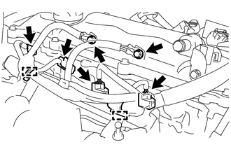
Remove the 2 bolts and disconnect the ground wire from the cylinder head cover sub-assembly.
-
Disconnect the 4 fuel injector assembly connectors.
-
Disengage the 2 wire harness clamps.
-
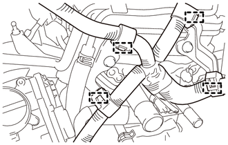
Disengage the 4 wire harness clamps from the wire harness bracket.
-
Remove the 2 bolts and 2 wire harness brackets from the cylinder head sub-assembly.
-
-
DISCONNECT FUEL TUBE SUB-ASSEMBLY
-
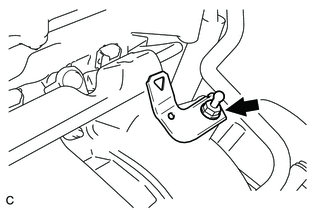
Type A:
-
Remove the No. 2 fuel pipe clamp.
Note
Do not reuse the No. 2 fuel pipe clamp.
-
-
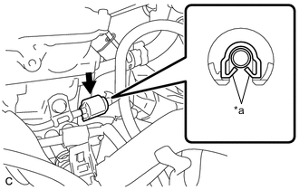
*a Claw Type B:
-
Remove the No. 2 fuel pipe clamp.
Note
Do not reuse the No. 2 fuel pipe clamp.
-
-

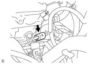
*a Retainer (4 places) Using SST (fuel hose puller), disconnect the fuel tube sub-assembly.
- SST
- 09268-21011
Note
-
Check for foreign matter on the fuel tube around the fuel tube connector. Clean it if necessary. Foreign matter can affect the ability of the O-rings to seal the fuel tube connector and fuel pipe.
-
Do not forcibly bend, kink or twist the fuel tube.
-
Keep the fuel tube connector and fuel pipe free from foreign matter.
-
If the fuel tube connector and fuel pipe are stuck together, pinch the fuel tube connector and turn it carefully to disconnect it.
-
Cover the fuel tube connector and fuel pipe with plastic bags to prevent damage and contamination.
-
-
REMOVE FUEL DELIVERY PIPE SUB-ASSEMBLY
-
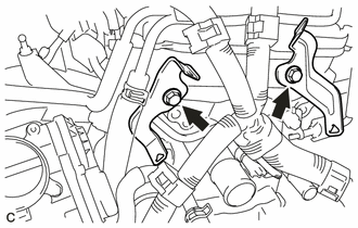
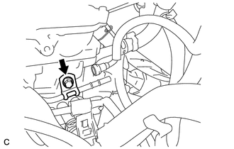
Remove the engine cover joint and wire harness bracket from the intake manifold.
-
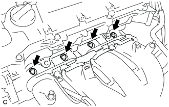
Remove the bolt from the cylinder head sub-assembly.
-
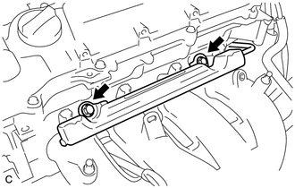
Remove the 2 bolts and fuel delivery pipe sub-assembly with the 4 fuel injector assemblies.
Note
Be careful not to drop the fuel injector assemblies when removing the fuel delivery pipe sub-assembly.
-
-
REMOVE NO. 1 DELIVERY PIPE SPACER
-
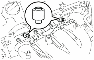
Remove the 2 No. 1 delivery pipe spacers from the cylinder head.
-
-
REMOVE FUEL INJECTOR ASSEMBLY
-
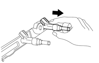
Pull the 4 fuel injector assemblies out of the fuel delivery pipe sub-assembly.
-
Remove the O-ring from each fuel injector assembly.
-
For reinstallation, attach a tag or label with the corresponding cylinder number to each fuel injector assembly.
Note
Protect the fuel injector assemblies by covering them with plastic bags.
-
Remove the 4 injector vibration insulators.
-