FUEL TANK INSTALLATION
PROCEDURE
-
INSTALL FUEL TANK MAIN TUBE SUB-ASSEMBLY
-
Engage the 2 claws to install the fuel tank main tube sub-assembly to the fuel tank assembly.
-
-
INSTALL FUEL RETURN TUBE SUB-ASSEMBLY
-
Engage the 2 claws to install the fuel return tube sub-assembly to the fuel tank assembly.
-
-
INSTALL NO. 2 FUEL TANK CUSHION (w/ No. 2 Fuel Tank Cushion)
-
Install a new No. 2 fuel tank cushion to the fuel tank assembly.
-
-
INSTALL NO. 1 FUEL TANK CUSHION
-
Install a new No. 1 fuel tank cushion to the fuel tank assembly.
-
-
INSTALL FUEL TANK ASSEMBLY
-
Set the fuel tank assembly on an engine lifter.
-
Using the engine lifter, slowly raise the fuel tank assembly, and then temporarily install the fuel tank assembly with the 4 bolts.
Note
-
Be careful not to drop the fuel tank assembly.
-
When installing the fuel tank assembly, tilt it slightly to prevent it from interfering with the surrounding parts.
-
-
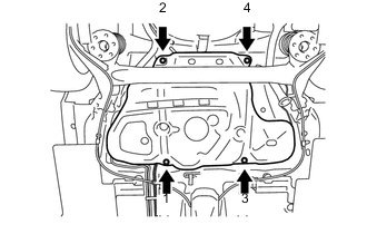
Tighten the 4 bolts in the order shown in the illustration.
- Torque:
- 39.2 N*m { 400 kgf*cm, 29 ft.*lbf }
-
Connect the parking brake cable assembly with the 2 bolts.
- Torque:
- 6.0 N*m { 61 kgf*cm, 53 in.*lbf }
-
-
CONNECT FUEL TANK MAIN TUBE SUB-ASSEMBLY
Note
Check that there is no damage or foreign matter on the connecting parts of the fuel lines.
-
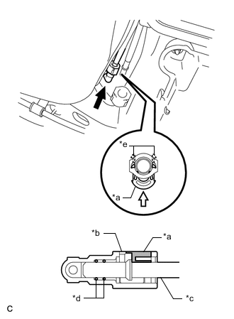
*a Retainer *b Fuel Tube Connector *c Fuel Pipe *d O-ring *e Claw 
Push 
Push in Connect the fuel tank main tube sub-assembly to the fuel pipe.
-
Align the fuel tube connector with the fuel pipe, and push them together until the fuel tube connector makes a "click" sound. If it is difficult to push the fuel pipe into the fuel tube connector, apply a small amount of clean fuel to the tip of the fuel pipe and reinsert it.
-
Connect the fuel lines and push in the retainer to engage the 2 claws. Check that the fuel pipe and fuel tube connector are securely connected by pulling on them.
-
-
-
CONNECT FUEL RETURN TUBE SUB-ASSEMBLY (w/ Glow Plug Controller)
Note
Check that there is no damage or foreign matter on the connecting parts of the fuel lines.
-
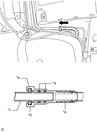
*a Retainer *b Fuel Tube Connector *c Fuel Pipe *d O-ring *e Nylon Tube Push Connect the fuel return tube sub-assembly to the fuel pipe.
-
Align the fuel tube connector with the fuel pipe, and push them together until the fuel tube connector makes a "click" sound. If it is difficult to push the fuel pipe into the fuel tube connector, apply a small amount of clean fuel to the tip of the fuel pipe and reinsert it.
-
After connecting the fuel lines, check that the fuel pipe and fuel tube connector are securely connected by pulling on them.
-
-
-
CONNECT FUEL RETURN TUBE SUB-ASSEMBLY (w/o Glow Plug Controller)
Note
Check that there is no damage or foreign matter on the connecting parts of the fuel lines.
-
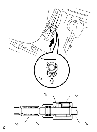
*a Retainer *b Fuel Tube Connector *c Fuel Pipe *d O-ring *e Nylon Tube *f Claw Push Push in Connect the fuel return tube sub-assembly to the fuel pipe.
-
Align the fuel tube connector with the fuel pipe, and push them together until the fuel tube connector makes a "click" sound. If it is difficult to push the fuel pipe into the fuel tube connector, apply a small amount of clean fuel to the tip of the fuel pipe and reinsert it.
-
Connect the fuel lines and push in the retainer to engage the 2 claws. Check that the fuel pipe and fuel tube connector are securely connected by pulling on them.
-
-
-
CONNECT FUEL TANK TO FILLER PIPE HOSE
-
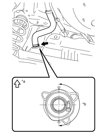
*a Up *b 180° (Clamp Bolt Area) Connect the fuel tank to filler pipe hose to the fuel tank assembly and tighten the clamp to secure it.
Tech Tips
Make sure the bolt of the clamp is positioned within the area shown in the illustration.
-
-
CONNECT FUEL TANK BREATHER TUBE
-
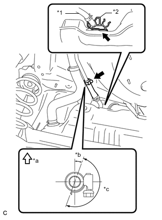
*1 Fuel Tank Breather Tube *2 Evaporation Vent Tube Clamp *a Up *b 20° *c 180° (Clamp Bolt Area) Connect the fuel tank breather tube to the fuel tank filler pipe sub-assembly and tighten the clamp to secure it.
Note
After connecting the fuel tank breather tube, check that the evaporation vent tube clamp is securely connected to the fuel tank assembly.
Tech Tips
Make sure the bolt of the clamp is positioned within the area shown in the illustration.
-
-
INSTALL NO. 1 FUEL TANK PROTECTOR
-
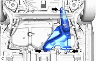
Bolt Nut Temporarily install the No. 1 fuel tank protector with the 3 bolts and nut.
-
Tighten the No. 1 fuel tank protector with the 3 bolts and nut in the order shown in the illustration.
- Torque:
- 5.5 N*m { 56 kgf*cm, 49 in.*lbf }
-
-
INSTALL CENTER EXHAUST PIPE ASSEMBLY
-
INSTALL REAR NO. 1 FLOOR UNDER COVER
-
Install the rear No. 1 floor under cover with the 2 grommets.
-
Install the 4 clips and nut.
-
-
INSTALL REAR FLOOR SIDE MEMBER BRACE SUB-ASSEMBLY
-
INSTALL REAR FLOOR SIDE MEMBER COVER LH (w/ Cover)
-
INSTALL REAR FLOOR SIDE MEMBER COVER RH (w/ Cover)
-
INSTALL FUEL TANK VENT TUBE SUB-ASSEMBLY (except Sedan)
-
INSTALL FUEL TANK VENT TUBE SUB-ASSEMBLY (for Sedan)
-
ADD FUEL
-
INSPECT FOR EXHAUST GAS LEAK