FUEL SUPPLY PUMP(w/ Glow Plug Controller) INSTALLATION
CAUTION / NOTICE / HINT
Note
-
When replacing the injector assemblies (including exchanging the injector assemblies between the cylinders), common rail assembly, intake manifold or cylinder head sub-assembly, it is necessary to replace the injection pipe sub-assemblies with new ones.
-
When replacing the injector assemblies, supply pump assembly, common rail assembly, intake manifold or cylinder head sub-assembly, it is necessary to replace the fuel inlet pipe sub-assembly with a new one.
PROCEDURE
-
INSTALL NO. 3 NOZZLE LEAKAGE PIPE
-
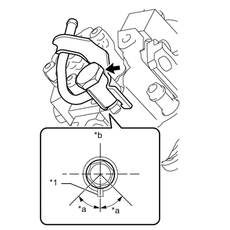
*1 Gasket *a 45° *b Up Install a new gasket and No. 3 nozzle leakage pipe to the supply pump assembly with the union bolt.
- Torque:
- 25 N*m { 255 kgf*cm, 18 ft.*lbf }
Note
-
Install the gasket within the area shown in the illustration.
-
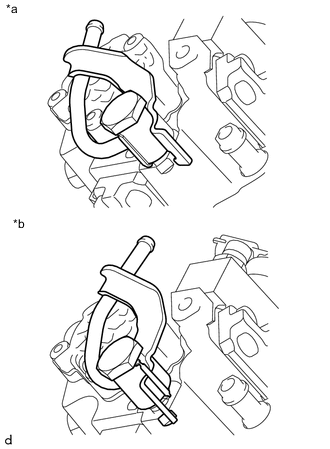
*a Correct *b Incorrect When installing, make sure the detent portion of the No. 3 nozzle leakage pipe is in the location as shown in the illustration.
-
-
INSTALL NO. 4 NOZZLE LEAKAGE PIPE
-
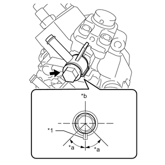
*1 Gasket *a 45° *b Up Install a new gasket and No. 4 nozzle leakage pipe to the supply pump assembly with the union bolt.
- Torque:
- 20 N*m { 204 kgf*cm, 15 ft.*lbf }
Note
Install the gasket within the area shown in the illustration.
-
-
INSTALL SUPPLY PUMP ASSEMBLY
-
Install the supply pump drive coupling to the supply pump assembly.
-
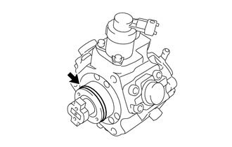
Apply a light coat of engine oil to the O-ring.
Note
If reusing the supply pump assembly, be sure to inspect the O-ring.
-
Install the supply pump assembly to the cylinder head sub-assembly with the 3 bolts.
- Torque:
- 21 N*m { 214 kgf*cm, 15 ft.*lbf }
-
-
INSTALL FUEL PUMP PROTECTOR
-
Install the fuel pump protector to the supply pump assembly with the 2 bolts.
- Torque:
- 10.3 N*m { 105 kgf*cm, 8 ft.*lbf }
-
-
INSTALL NO. 2 NOZZLE LEAKAGE PIPE
-
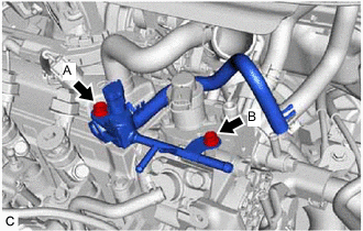
Install the No. 2 nozzle leakage pipe to the cylinder head cover sub-assembly and supply pump assembly with the 2 bolts.
- Torque:
- Bolt (A)
- 21 N*m { 214 kgf*cm, 15 ft.*lbf }
- Bolt (B)
- 9.0 N*m { 92 kgf*cm, 80 in.*lbf }
-
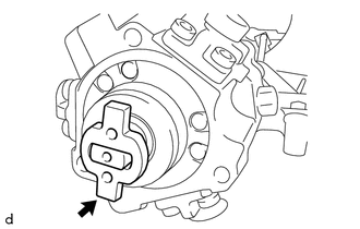
Connect the fuel temperature sensor connector.
-
Connect the No. 2 fuel hose to the No. 2 nozzle leakage pipe and slide the clip to secure it.
-
Install the wiring harness clamp bracket to the fuel pump protector with the bolt.
- Torque:
- 8.0 N*m { 82 kgf*cm, 71 in.*lbf }
-
Engage the clamp to connect the wire harness to the wiring harness clamp bracket.
-
Connect the supply pump assembly connector.
-
Connect the fuel hose to the No. 4 nozzle leakage pipe and slide the clip to secure it.
-
-
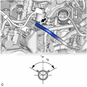
CONNECT NO. 1 FUEL HOSE
-
*a Front *b 120° Connect the No. 1 fuel hose to the No. 3 nozzle leakage pipe and slide the clip to secure it.
Tech Tips
Engage the clip within the area shown in the illustration.
-
Engage the clamp.
-
-
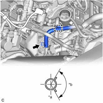
CONNECT NO. 2 FUEL HOSE
-
*a Up *b 120° Connect the No. 2 fuel hose to the No. 2 nozzle leakage pipe and slide the clip to secure it.
Tech Tips
Engage the clip within the area shown in the illustration.
-
-
INSTALL FUEL INLET PIPE SUB-ASSEMBLY
-
INSTALL NO. 3 INJECTION PIPE SUB-ASSEMBLY
-
INSTALL NO. 2 INJECTION PIPE SUB-ASSEMBLY
-
INSTALL NO. 1 INJECTION PIPE SUB-ASSEMBLY
-
INSTALL NOZZLE LEAKAGE PIPE ASSEMBLY
-
INSTALL NO. 1 VACUUM SWITCHING VALVE ASSEMBLY
-
INSTALL NO. 1 GLOW PLUG CONNECTOR
-
INSTALL AIR CLEANER CASE SUB-ASSEMBLY
-
INSTALL AIR CLEANER CAP SUB-ASSEMBLY
-
PERFORM INITIALIZATION AND REGISTRATION
-
BLEED AIR FROM FUEL SYSTEM
-
INSPECT FOR FUEL LEAK
-
INSTALL NO. 1 ENGINE COVER (w/ No. 1 Engine Cover)