SUCTION CONTROL VALVE INSTALLATION
CAUTION / NOTICE / HINT
Tech Tips
After replacing the suction control valve, perform the "SUPPLY PUMP INITIALIZATION PROCEDURE" function using the GTS.
PROCEDURE
-
INSTALL SUCTION CONTROL VALVE ASSEMBLY
Note
-
Before replacing the suction control valve assembly, be sure to clean the area around it.
-
When replacing the suction control valve assembly, make sure that your hands are clean. Do not use gloves, etc.
-
Apply a light coat of engine oil to a new O-ring.
Note
Only use clean engine oil.
-
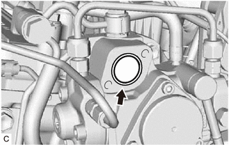
Install the O-ring to the O-ring groove of the fuel supply pump assembly.
Note
Make sure that the O-ring and O-ring groove are free of foreign matter and are not damaged.
-
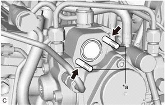
*a Guide Pin Install the guide pins used for the insertion of the suction control valve assembly to the bolt holes.
Tech Tips
-
When installing the guide pins, secure them lightly in place by hand.
-
The guide pins are used to make sure that the suction control valve assembly is perpendicular to the fuel supply pump assembly when it is inserted.
-
-
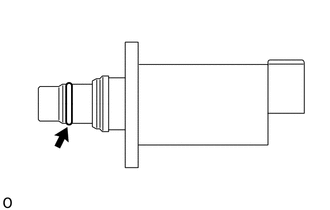
Apply a light coat of engine oil to the O-ring at the end of the suction control valve assembly.
Note
Only use clean engine oil.
-
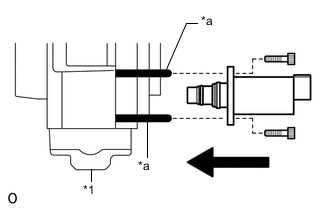
*1 Fuel Supply Pump Assembly *a Guide Pin While making sure that the suction control valve assembly and fuel supply pump assembly are perpendicular to each other, slide the suction control valve assembly along the guide pins and insert it into the fuel supply pump assembly as shown in the illustration.
Note
-
Make sure that the contact surfaces of the fuel supply pump assembly and suction control valve assembly are free of foreign matter and are not damaged.
-
Do not insert the suction control valve assembly at an angle.
-
Make sure that the O-ring does not get pinched between the parts. If it does, replace it with a new one.
-
Insert the suction control valve assembly until it contacts the fuel supply pump assembly.
-
-
While holding the suction control valve assembly in place, remove the guide pins, temporarily install 2 new bolts and uniformly tighten them by hand.
Note
Do not use any tools. Tighten the bolts by hand until the surfaces of the suction control valve assembly and fuel supply pump assembly contact each other.
-
Using a 5 mm hexagon wrench, uniformly tighten the 2 bolts.
- Torque:
- 9.0 N*m { 92 kgf*cm, 80 in.*lbf }
-
Connect the connector to the suction control valve assembly.
Note
Make sure that there is no excessive slack or tension in the wire harness of the suction control valve assembly.
-
-
INSTALL AIR CLEANER CASE SUB-ASSEMBLY
-
INSTALL AIR CLEANER CAP SUB-ASSEMBLY
-
BLEED AIR FROM FUEL SYSTEM
-
SUPPLY PUMP INITIALIZATION PROCEDURE
-
INSPECT FOR FUEL LEAK
-
INSTALL NO. 1 ENGINE COVER