FUEL SUPPLY PUMP INSTALLATION
CAUTION / NOTICE / HINT
Note
-
When replacing the injector assemblies (including exchanging the injector assemblies between the cylinders), common rail assembly, intake manifold or cylinder head, it is necessary to replace the injection pipes with new ones.
-
When replacing the supply pump assembly, common rail assembly, intake manifold or cylinder head, it is necessary to replace the fuel inlet pipe with a new one.
Tech Tips
After replacing the supply pump assembly, perform the "SUPPLY PUMP INITIALIZATION PROCEDURE" function using the GTS.
PROCEDURE
-
INSTALL SUPPLY PUMP ASSEMBLY
-
Apply a light coat of engine oil to a new O-ring.
-
Install the O-ring to the supply pump assembly.
-
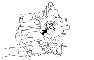
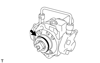
Install the supply pump drive coupling.
Note
When reusing the coupling, install in the same orientation (top/bottom, front/back) as when it was removed.
Tech Tips
Line up the coupling with the groove in the camshaft end.
-
Install the supply pump assembly with the 2 bolts.
- Torque:
- 20.5 N*m { 209 kgf*cm, 15 ft.*lbf }
Tech Tips
Line up the end of the supply pump drive shaft with the supply pump drive coupling.
-
Connect the suction control valve assembly connector.
-
Connect the fuel temperature sensor connector.
-
-
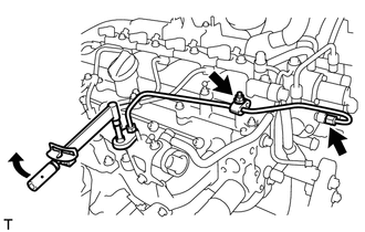
INSTALL FUEL TUBE SUB-ASSEMBLY
-
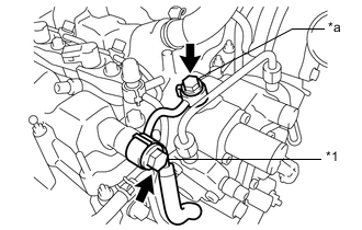
*1 Check Valve *a Union Bolt Temporarily install the fuel tube sub-assembly with 2 new gaskets, the check valve and union bolt.
-
Tighten the check valve.
- Torque:
- 31.5 N*m { 321 kgf*cm, 23 ft.*lbf }
-
Tighten the union bolt.
- Torque:
- 23 N*m { 235 kgf*cm, 17 ft.*lbf }
-
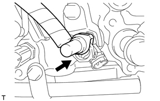
Insert the fuel tube connector into the exhaust fuel addition injector assembly.
-
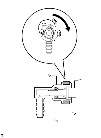
*1 Exhaust Fuel Addition Injector Assembly *a Fuel Tube Connector *b Retainer *c O-ring Turn the retainer as shown in the illustration until it makes a "click" sound.
Note
-
If the fuel tube connector is not connected to the exhaust fuel addition injector assembly in the correct position, the retainer cannot be turned further in the direction indicated by the arrow.
-
Check that there are no scratches or foreign matter around the connecting parts of the fuel tube connector and exhaust fuel addition injector assembly before performing this work.
-
After connecting the fuel tube connector, check that the fuel tube connector is securely connected by pulling on the fuel tube connector.
-
-
Connect the exhaust fuel addition injector assembly connector.
-
-
INSTALL FUEL HOSE PROTECTOR
-
INSTALL FUEL INLET PIPE SUB-ASSEMBLY
-
Temporarily install the fuel inlet pipe sub-assembly with the 2 clamps and nut.
-
Using a 14 mm union nut wrench, tighten the nut at the common rail assembly end of the fuel inlet pipe sub-assembly.
- Torque:
- 30 N*m { 306 kgf*cm, 22 ft.*lbf }
Note
Use the torque value compensation formula to calculate the torque value for use when a torque wrench is combined with a tool such as a union nut wrench.
-
Using a 14 mm union nut wrench, tighten the nut at the supply pump assembly end of the fuel inlet pipe sub-assembly.
- Torque:
- 30 N*m { 306 kgf*cm, 22 ft.*lbf }
Note
Use the torque value compensation formula to calculate the torque value for use when a torque wrench is combined with a tool such as a union nut wrench.
-
Tighten the injection pipe clamp nut.
- Torque:
- 5.0 N*m { 51 kgf*cm, 44 in.*lbf }
-
-
INSTALL NO. 1 FUEL HOSE
-
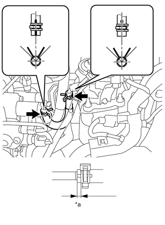
*a 1 to 5 mm Connect the No. 1 fuel hose, then slide the 2 clips to secure it.
Tech Tips
-
Align the alignment marks and connect the hose.
-
Align the tabs of the clip with the alignment mark of the hose and connect the hose.
-
Position the clip so that the distance is 1 to 5 mm (0.0394 to 0.197 in.).
-
-
-
INSTALL NO. 3 FUEL HOSE
-
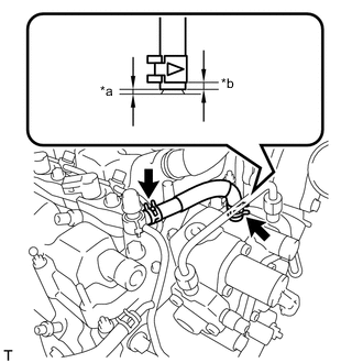
*a 2 to 3 mm *b 2 to 6 mm Install the No. 3 fuel hose, then fit it with the 2 clips as shown in the illustration.
Tech Tips
-
Push in the fuel hose so that the distance is 2 to 3 mm (0.0787 to 0.118 in.).
-
Position the clamp so that the distance is 2 to 6 mm (0.0787 to 0.236 in.).
-
-
-
INSTALL AIR CLEANER CASE SUB-ASSEMBLY
-
INSTALL AIR CLEANER CAP SUB-ASSEMBLY
-
CONNECT CABLE TO NEGATIVE BATTERY TERMINAL
Note
When disconnecting the cable, some systems need to be initialized after the cable is reconnected.
-
PERFORM INITIALIZATION
-
Perform supply pump assembly initialization procedure.
-
-
BLEED AIR FROM FUEL SYSTEM
-
INSPECT FOR FUEL LEAK
-
INSTALL NO. 1 ENGINE COVER