FUEL INJECTOR INSTALLATION
CAUTION / NOTICE / HINT
Note
When replacing the injector assemblies (including exchanging the injector assemblies between the cylinders), it is necessary to replace the injection pipe sub-assemblies with new ones.
Tech Tips
After replacing any of the injector assemblies, perform both the "Injector Compensation" and the "Pilot Quantity Learning Values Reset" functions using the GTS.
PROCEDURE
-
INSTALL INJECTOR ASSEMBLY
Note
Before installing the injector assembly, check for carbon, foreign matter, etc. on the sealing surfaces of the cylinder head and injector assembly. Clean them if necessary.
-
Install 4 new injection nozzle seats to the cylinder head.
-
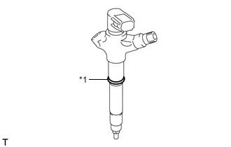
*1 O-ring Install new O-rings to each injector assembly.
-
Apply a light coat of engine oil to the O-rings on each injector assembly.
-
Install the 4 injector assemblies to the cylinder head.
Note
Fit the injector assemblies to the injection nozzle seats.
-
-
INSTALL NO. 1 NOZZLE HOLDER CLAMP
-
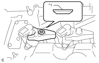
*1 Washer Install the No. 1 nozzle holder clamps and washers as shown in the illustration.
Note
Be careful of the mounting orientation (beveled edge) of the washer.
-
Temporarily install the nozzle holder clamp bolts.
Note
When temporarily installing the nozzle holder clamps and No. 1 nozzle holder clamp bolts, be careful not to position them at an angle.
Tech Tips
Apply a light coat of engine oil to the threads of the nozzle holder clamp bolts.
-
Temporarily install the No. 1 nozzle leakage pipe with 4 new gaskets, the 4 union bolts and bolt.
-
Temporarily install the injection pipe sub-assembly.
-
Tighten the 4 nozzle holder clamp bolts.
- Torque:
- 25 N*m { 255 kgf*cm, 18 ft.*lbf }
-
-
INSTALL NO. 1 NOZZLE LEAKAGE PIPE
-
Tighten the 4 union bolts.
- Torque:
- 18 N*m { 184 kgf*cm, 13 ft.*lbf }
-
Tighten the bolt.
- Torque:
- 20.5 N*m { 209 kgf*cm, 15 ft.*lbf }
-
-
INSTALL INJECTION PIPE SUB-ASSEMBLY
-
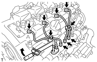
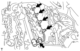
Using a 14 mm union nut wrench, tighten the 4 nuts at the common rail assembly end of the injection pipe sub-assemblies.
- Torque:
- 30 N*m { 306 kgf*cm, 22 ft.*lbf }
Note
Use the torque value compensation formula to calculate the torque value for use when a torque wrench is combined with a tool such as a union nut wrench.
-
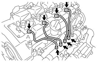
Using a 14 mm union nut wrench, tighten the 4 nuts at the injector assembly end of the injection pipe sub-assemblies.
- Torque:
- 30 N*m { 306 kgf*cm, 22 ft.*lbf }
Note
Use the torque value compensation formula to calculate the torque value for use when a torque wrench is combined with a tool such as a union nut wrench.
-
Install the 4 injection pipe clamps with the 2 bolts.
- Torque:
- 5.0 N*m { 51 kgf*cm, 44 in.*lbf }
-
-
INSTALL NO. 2 NOZZLE LEAKAGE PIPE
-
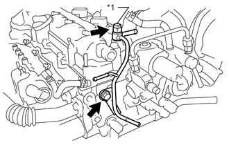
*1 Check Valve Temporarily install the No. 2 nozzle leakage pipe with a new gasket, the check valve and bolt.
-
Tighten the check valve.
- Torque:
- 31.5 N*m { 321 kgf*cm, 23 ft.*lbf }
-
Tighten the bolt.
- Torque:
- 31.5 N*m { 321 kgf*cm, 23 ft.*lbf }
-
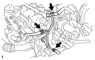
Connect the 3 fuel hoses with the 3 clips.
-
-
INSTALL FUEL TUBE SUB-ASSEMBLY
-
INSTALL FUEL HOSE PROTECTOR
-
CONNECT ENGINE WIRE
-
Connect the engine wire with the bolt and 5 nuts.
- Torque:
- 8.0 N*m { 82 kgf*cm, 71 in.*lbf }
-
Install the 2 wire harness brackets with the 2 bolts.
- Torque:
- 12.5 N*m { 127 kgf*cm, 9 ft.*lbf }
-
Engage the 2 wire harness clamps.
-
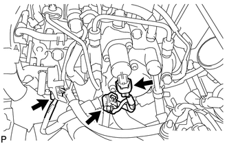
Connect the glow plug connector.
-
Connect the connector to the pressure control valve.
-
Connect the connector to the fuel pressure sensor.
-
Connect the 3 connectors.
-
Connect the 4 connectors to the 4 injector assemblies.
-
-
INSTALL AIR CLEANER CASE SUB-ASSEMBLY
-
INSTALL AIR CLEANER CAP SUB-ASSEMBLY
-
CONNECT CABLE TO NEGATIVE BATTERY TERMINAL
Note
When disconnecting the cable, some systems need to be initialized after the cable is reconnected.
-
PERFORM REGISTRATION AND INITIALIZATION
-
Perform registration of injector assembly compensation codes.
-
Perform registration of pilot quantity learning.
-
-
BLEED AIR FROM FUEL SYSTEM
-
INSPECT FOR FUEL LEAK
-
INSTALL NO. 1 ENGINE COVER
-
INSTALL OUTER COWL TOP PANEL
-
INSTALL DIFFERENTIAL PRESSURE SENSOR ASSEMBLY
-
INSTALL NO. 2 HEATER AIR DUCT SPLASH SHIELD SEAL
-
INSTALL WATER GUARD PLATE LH
-
INSTALL WINDSHIELD WIPER MOTOR AND LINK ASSEMBLY