FUEL INJECTOR REMOVAL
CAUTION / NOTICE / HINT
Note
When replacing the injector assemblies (including exchanging the injector assemblies between the cylinders), common rail assembly, intake manifold or cylinder head, it is necessary to replace the injection pipe sub-assemblies with new ones.
Tech Tips
After replacing any of the injector assemblies, perform both the "Injector Compensation" and the "Pilot Quantity Learning Values Reset" functions using the GTS.
PROCEDURE
-
PRECAUTION
Note
After turning the ignition switch off, waiting time may be required before disconnecting the cable from the negative (-) battery terminal. Therefore, make sure to read the disconnecting the cable from the negative (-) battery terminal notice before proceeding with work.
-
DISCONNECT CABLE FROM NEGATIVE BATTERY TERMINAL
Note
When disconnecting the cable, some systems need to be initialized after the cable is reconnected.
-
REMOVE WINDSHIELD WIPER MOTOR AND LINK ASSEMBLY
-
REMOVE WATER GUARD PLATE LH
-
REMOVE NO. 2 HEATER AIR DUCT SPLASH SHIELD SEAL
-
SEPARATE DIFFERENTIAL PRESSURE SENSOR ASSEMBLY
-
REMOVE OUTER COWL TOP PANEL
-
REMOVE NO. 1 ENGINE COVER
-
REMOVE AIR CLEANER CAP SUB-ASSEMBLY
-
REMOVE AIR CLEANER CASE SUB-ASSEMBLY
-
SEPARATE ENGINE WIRE
-
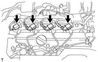
Disconnect the 4 connectors from the 4 injector assemblies.
-
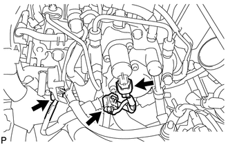
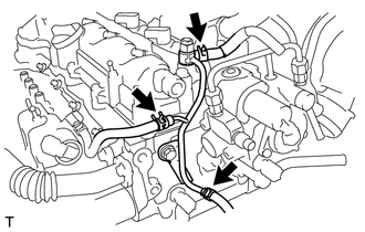
Disconnect the 3 connectors.
-
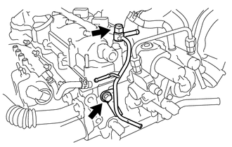
Disconnect the connector from the fuel pressure sensor.
-
Disconnect the connector from the pressure control valve.
-
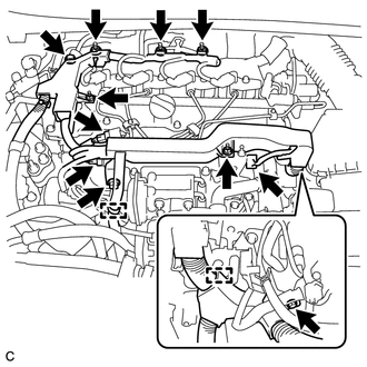
Disconnect the glow plug connector.
-
Disengage the 2 wire harness clamps.
-
Remove the 2 bolts and 2 wire harness brackets.
-
Remove the bolt and 5 nuts and disconnect the engine wire.
-
-
REMOVE INJECTION PIPE SUB-ASSEMBLY
Note
After removing the injection pipe sub-assembly, cover the common rail assembly with protective tape to prevent dirt or foreign matter from entering the pipe inlet. Also protect the injector inlets by covering them with protective tape or plastic bags.
-
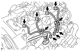
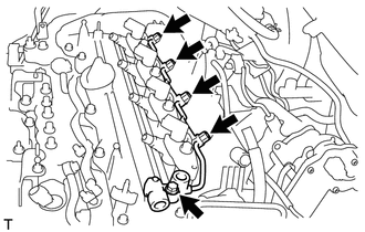
Remove the 2 bolts and 4 injection pipe clamps.
-
Using a 14 mm union nut wrench, loosen the 4 nuts at the common rail assembly end of the injection pipe sub-assemblies.
-
Using a 14 mm union nut wrench, loosen the 4 nuts at the injector end of the injection pipe sub-assemblies.
-
Remove the 4 injection pipe sub-assemblies.
-
-
REMOVE FUEL HOSE PROTECTOR
-
REMOVE FUEL TUBE SUB-ASSEMBLY
-
REMOVE NO. 2 NOZZLE LEAKAGE PIPE
-
Slide the 3 clips and disconnect the 3 fuel hoses.
-
Remove the check valve.
-
Remove the bolt and No. 2 nozzle leakage pipe with the gasket.
-
-
REMOVE NO. 1 NOZZLE LEAKAGE PIPE
-
Remove the 4 union bolts.
-
Remove the bolt and No. 1 nozzle leakage pipe with the 4 gaskets.
-
-
REMOVE NO. 1 NOZZLE HOLDER CLAMP
-
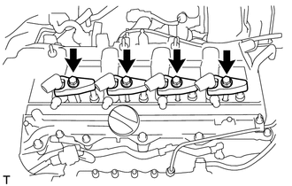
Remove the 4 bolts, 4 washers and 4 No. 1 nozzle holder clamps.
-
-
REMOVE INJECTOR ASSEMBLY
-
Remove the 4 injector assemblies and 4 injection nozzle seats from the cylinder head.
Note
Arrange the removed parts in the correct order so that they can be returned to their original locations when reassembling.
-
Remove the O-rings from each injector assembly.
-