CYLINDER BLOCK REASSEMBLY
CAUTION / NOTICE / HINT
Note
Before performing these installation procedures, sufficiently clean and remove any foreign matter from the cylinder block, connecting rod and other parts.
PROCEDURE
-
INSTALL NO. 1 OIL NOZZLE SUB-ASSEMBLY
-
Using a 5 mm hexagon wrench, install the 4 No. 1 oil nozzle sub-assemblies with the 4 bolts.
Tech Tips
Refer to "SPECIFICATIONS - STANDARD BOLT" for the tightening torque.
-
-
INSTALL PISTON WITH PIN SUB-ASSEMBLY
-
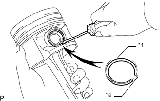
*1 Snap Ring *a Service Hole Cutout Portion Using a screwdriver, install a new snap ring on one side of the piston pin hole.
Tech Tips
Make sure that the end gap of the snap ring is not aligned with the service hole cutout portion of the piston sub-assembly.
-
Coat the piston pin with engine oil.
-
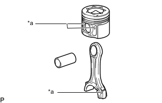
*a Matchmark Align the matchmarks of the piston sub-assembly and connecting rod sub-assembly, install the connecting rod sub-assembly to the piston sub-assembly and push in the piston pin with your thumb.
Tech Tips
The piston sub-assembly and piston pin are a matched set.
-
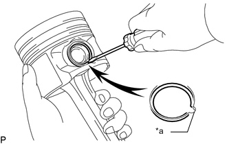
*a Service Hole Cutout Portion Using a screwdriver, install a new snap ring at the other end of the piston pin hole.
Tech Tips
Make sure that the end gap of the snap ring is not aligned with the service hole cutout portion of the piston.
-
Check the fitting condition between the piston sub-assembly and piston pin by trying to move the piston back and forth on the piston pin.
-
-
INSTALL PISTON RING SET
-
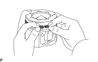
Install the oil ring expander by hand.
-
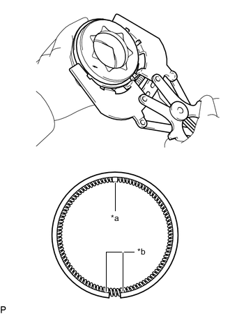
*a Coil Joint *b Oil Ring End Using a piston ring expander, install the oil ring rail.
Tech Tips
Make sure the end gap of the oil ring faces in the opposite direction of the coil joint.
-
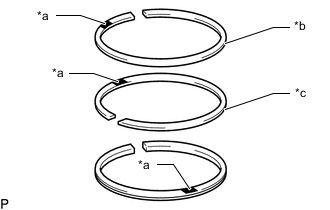
*a Code Mark (TOP) *b Plain Rectangular Compression Ring *c Taper-faced Compression Ring Using a piston ring expander, install the No. 1 compression ring and No. 2 compression ring so that the code marks are positioned as shown in the illustration.
Code Mark Item Mark No. 1 compression ring TOP No. 2 compression ring Oil ring rail Tech Tips
Install the No. 1 compression ring, No. 2 compression ring and oil ring rail with the code mark facing upward.
-
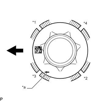
*1 No. 1 Compression Ring *2 No. 2 Compression Ring *3 Oil Ring Rail *4 Oil Ring Expander *a Front Mark 
Front Position the piston rings so that the ring ends are as shown in the illustration.
Note
Do not align the ring ends.
-
-
INSTALL CONNECTING ROD BEARING
Note
Apply engine oil to the inner surface of each connecting rod bearing (the surface which contacts the crankshaft assembly), but not to the outer surface (the surface which contacts the connecting rod sub-assembly or connecting rod cap).
-
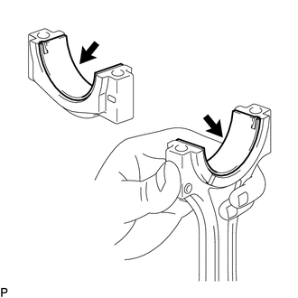
Install the connecting rod bearings to the connecting rod sub-assembly and connecting rod cap.
Note
-
Clean the backside of the connecting rod bearing and the connecting rod bearing seating surface of the connecting rod sub-assembly.
-
Make sure that there is no foreign matter or damage on the crank pin or connecting rod bearing.
-
Do not touch the crank pin or connecting rod bearing while wearing gloves.
-
-
-
INSTALL CRANKSHAFT BEARING
Note
-
Apply engine oil to the inner surface of each crankshaft bearing (the surface which contacts the crankshaft assembly), but not to the outer surface (the surface which contacts the crankshaft bearing cap or cylinder block).
-
When replacing a crankshaft bearing, also replace the corresponding upper crankshaft bearing or lower crankshaft bearing.
-
Clean each main journal and crankshaft bearing.
-
*a Claw Align the crankshaft bearing claw with the claw groove of the cylinder block, and push in the 4 upper crankshaft bearings to install them.
Note
-
Clean the contact surface of the crankshaft bearing and cylinder block.
-
Apply engine oil to the inner surface of each crankshaft bearing (the surface which contacts the crankshaft assembly), but not to the outer surface (the surface which contacts the cylinder block).
-
Make sure both sides of the oil grooves in the cylinder block are visible through the oil feed holes in the crankshaft bearing. Make sure the visible amount of each side of the holes is equal.
-
-
*a Claw Align the crankshaft bearing claw with the claw groove of the cylinder block, and push in the No. 3 upper crankshaft bearing to install the bearing.
Note
-
Clean the contact surface of the crankshaft bearing and cylinder block.
-
Apply engine oil to the inner surface of each crankshaft bearing (the surface which contacts the crankshaft assembly), but not to the outer surface (the surface which contacts the cylinder block).
-
Make sure both sides of the oil groove in the cylinder block are visible through the oil feed holes in the crankshaft bearing. Make sure the amount visible on each side of the holes is equal.
-
-
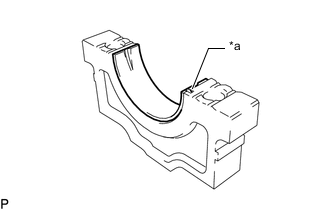
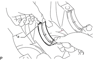
*a Claw Align the crankshaft bearing claw with the claw groove of the crankshaft bearing cap, and push in the 4 lower crankshaft bearings to install the bearing.
Note
-
Clean the contact surface of the crankshaft bearing and crankshaft bearing cap.
-
Apply engine oil to the inner surface of each crankshaft bearing (the surface which contacts the crankshaft assembly), but not to the outer surface (the surface which contacts the crankshaft bearing cap).
-
-
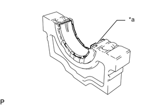
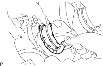
*a Claw Align the crankshaft bearing claw with the claw groove of the crankshaft bearing cap, and push in the No. 3 lower crankshaft bearing to install the bearing.
Note
-
Clean the contact surface of the crankshaft bearing and crankshaft bearing cap.
-
Apply engine oil to the inner surface of each crankshaft bearing (the surface which contacts the crankshaft assembly), but not to the outer surface (the surface which contacts the crankshaft bearing cap).
-
-
-
INSTALL CRANKSHAFT ASSEMBLY
-
Apply engine oil to the crankshaft bearings, and then place the main crankshaft bearing cap on the cylinder block.
Note
Do not apply oil to the crankshaft bearing cap bolt hole.
-
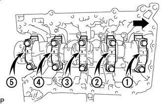
Front Set the crankshaft bearing caps on the crankshaft assembly as shown in the illustration.
Tech Tips
Make sure the crankshaft bearing caps are placed in the proper position and direction by checking the numbers on the caps.
-
Install new crankshaft bearing cap bolts.
Note
Do not reuse the crankshaft bearing cap bolt.
Tech Tips
The crankshaft bearing cap bolts are tightened in 2 progressive steps.
-
Step 1:
-
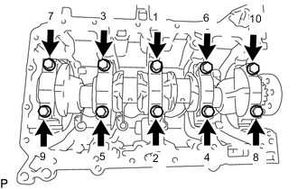
Uniformly tighten the 10 crankshaft bearing cap bolts in several steps in the sequence shown in the illustration.
- Torque:
- 25 N*m { 255 kgf*cm, 18 ft.*lbf }
-
Further tighten the 10 crankshaft bearing cap bolts in several steps in the sequence shown in the illustration.
- Torque:
- 50 N*m { 510 kgf*cm, 37 ft.*lbf }
-
-
Step 2:
-
Mark the front of each crankshaft bearing cap bolt head with paint.
-
Tighten the bearing cap bolts by 60° in the sequence shown in the illustration..
-
Further tighten the crankshaft bearing cap bolts by 60° in the sequence shown in the illustration.
-
Check that the paint marks are now at a 120° angle to the front.
-
-
Check that the crankshaft turns smoothly.
-
-
INSTALL PISTON SUB-ASSEMBLY WITH CONNECTING ROD SUB-ASSEMBLY
-
Apply engine oil to the cylinder walls, pistons and surfaces of the connecting rod bearings.
-
*1 No. 1 Compression Ring *2 No. 2 Compression Ring *3 Oil Ring Rail *4 Oil Ring Expander *a Front Mark Front Check the positions of the piston ring ends.
Note
Do not align the piston ring ends.
-
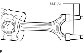
Install SST (A) to the connecting rod sub-assembly as shown in the illustration.
SST (A) PZ4TB-04961-44 Note
-
Make sure to use SST during the installation.
-
Guide the connecting rod sub-assembly using SST. Make sure that the connecting rod bearing is not damaged.
-
-
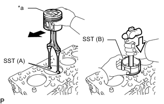
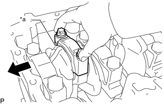
*a Front Mark Front 
Press Using a hammer handle and SST (B), press a piston and connecting rod sub-assembly into each cylinder with the front mark of the piston facing forward.
SST (B) PZ4TB-04935-82 -
Remove SST (A) from the connecting rod sub-assembly.
-
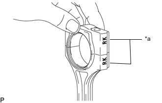
*a Matchmark Match the marked connecting rod cap with the connecting rod sub-assembly as shown in the illustration.
Note
Incorrect installation may result in damage to the connecting rod sub-assembly and crankshaft.
-
*a Front Mark (F) Front Install the connecting rod cap so that its front mark (F) is facing the correct direction.
Note
-
Make sure that the front mark of the connecting rod cap is facing forward.
-
Match the numbered connecting rod cap with the connecting rod sub-assembly.
-
Make sure that there is no foreign matter or damage on the crank pin or connecting rod bearing.
-
Do not touch the crank pin or connecting rod bearing while wearing gloves.
-
-
Apply a light coat of engine oil to the threads and under the heads of new connecting rod cap bolts.
Note
-
Do not reuse the connecting rod cap bolts.
-
Clean the threads of the connecting rod cap bolts.
-
-
Step 1:
-
Install and alternately tighten the connecting rod cap bolts in several steps.
- Torque:
- 20 N*m { 204 kgf*cm, 15 ft.*lbf }
-
-
Step 2:
-
Mark the front side of each connecting rod cap bolt with paint.
-
Tighten the connecting rod cap bolts by 70°.
-
Check that the paint marks are now at a 70° angle to the front.
-
-
Check that the crankshaft turns smoothly.
-