FUEL INJECTOR(w/ Glow Plug Controller) INSTALLATION
CAUTION / NOTICE / HINT
Note
-
When replacing the injector assemblies (including exchanging the injector assemblies between the cylinders), common rail assembly, intake manifold or cylinder head sub-assembly, it is necessary to replace the injection pipe sub-assemblies with new ones.
-
When replacing the injector assemblies, supply pump assembly, common rail assembly, intake manifold or cylinder head sub-assembly, it is necessary to replace the fuel inlet pipe sub-assembly with a new one.
Tech Tips
After replacing any of the injector assemblies, perform both the "Injector Compensation" and the "Pilot Quantity Learning Values Reset" functions using the GTS.
PROCEDURE
-
INSTALL INJECTION NOZZLE SEAT
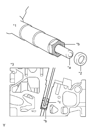
*1 Injector Assembly *2 Injection Nozzle Seat *3 Cylinder Head Sub-assembly *a Injector Nozzle *b Sealing Surface *c Cloth Note
-
When installing, clean the sealing surface of the injector assembly, injection pipe sub-assembly and common rail assembly.
-
When replacing the injector assemblies, the injection pipe sub-assemblies must also be replaced.
-
Replace the injection pipe sub-assembly with a new one when the injection pipe sub-assembly has been removed and reinstalled more than 5 times.
-
Replace the injector assembly with one with the same part number and install it to the cylinder head sub-assembly.
-
Using a cloth and solvent, wipe away any carbon from the sealing surface of the injector assembly and injector assembly installation hole, as shown in the illustration.
Note
-
Do not damage the sealing surface.
-
Do not touch the injector nozzle.
-
-
Install 4 new injection nozzle seats to the cylinder head sub-assembly.
-
-
INSTALL INJECTOR ASSEMBLY
-
Install the 4 injector assemblies to the cylinder head sub-assembly.
Note
Fit the injector assemblies to the injection nozzle seats.
-
-
INSTALL NOZZLE HOLDER CLAMP SEAT
-
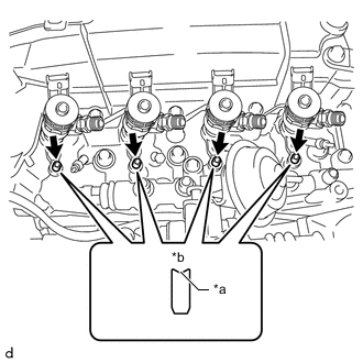
*a Concave *b Upper Side Install the 4 nozzle holder clamp seats to the cylinder head sub-assembly.
Note
Install the nozzle holder clamp seats with the concave end facing up.
-
-
INSTALL NO. 1 NOZZLE HOLDER CLAMP
-
Install the 4 No. 1 nozzle holder clamps to the injector assemblies and nozzle holder clamp seats.
-
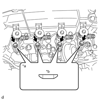
*a Cutaway View *b Upper Side Install the 4 washers to the No. 1 nozzle holder clamps.
Note
Install the washer in the correct direction.
-
Temporarily install the 4 bolts.
Tech Tips
Fully tighten the bolts when installing each injection pipe sub-assembly.
-
-
INSTALL NO. 4 INJECTION PIPE SUB-ASSEMBLY
Note
To prevent contamination by foreign matter, do not remove the plastic bag that is protecting the connector portion of the injector assembly and common rail assembly until immediately before installing the No. 4 injection pipe sub-assembly.
-

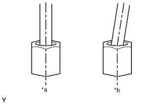
*a Correct *b Incorrect Temporarily install a new No. 4 injection pipe sub-assembly to the injector assembly and common rail assembly.
Note
-
When installing, the sealing surface of the No. 4 injection pipe sub-assembly should be fitted tightly against the injector assembly and common rail assembly.
-
When installing, do not tilt or angle the sealing surface of the No. 4 injection pipe sub-assembly.
-
When installing, tighten the union nut of the No. 4 injection pipe sub-assembly by hand until it cannot be turned any further.
-
-
Tighten the bolt of the No. 1 nozzle holder clamp.
- Torque:
- 19 N*m { 194 kgf*cm, 14 ft.*lbf }
-
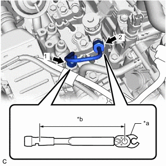
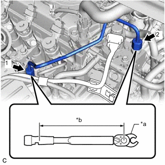
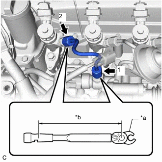
*a 17 mm Union Nut Wrench *b Torque Wrench Fulcrum Length Using a 17 mm union nut wrench, fully tighten the 2 union nuts in the order shown in the illustration.
- Torque:
- Specified tightening torque
- 28 N*m { 286 kgf*cm, 21 ft.*lbf }
Note
When fully tightening the union nuts, make sure to tighten from the common rail assembly side.
Tech Tips
-
Calculate the torque wrench reading when changing the fulcrum length of the torque wrench.
-
When using a 17 mm union nut wrench (fulcrum length of 30 mm (1.18 in.)) + torque wrench (fulcrum length of 180 mm (7.09 in.)): 24 N*m (245 kgf*cm, 18 ft.*lbf)
-
-
INSTALL FUEL INLET PIPE SUB-ASSEMBLY
Note
To prevent contamination by foreign matter, do not remove the plastic bag that is protecting the connector portion of the injector assembly and common rail assembly until immediately before installing the fuel inlet pipe sub-assembly.
-
*a Correct *b Incorrect Temporarily install a new fuel inlet pipe sub-assembly to the supply pump assembly and common rail assembly.
Note
-
When installing, the sealing surface of the fuel inlet pipe sub-assembly should be fitted tightly against the injector assembly and common rail assembly.
-
When installing, do not tilt or angle the sealing surface of the fuel inlet pipe sub-assembly.
-
When installing, tighten the union nut of the fuel inlet pipe sub-assembly by hand until it cannot be turned any further.
-
-
Tighten the bolt of the No. 1 nozzle holder clamp.
- Torque:
- 19 N*m { 194 kgf*cm, 14 ft.*lbf }
-
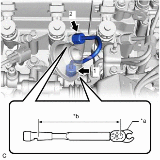
*a 17 mm Union Nut Wrench *b Torque Wrench Fulcrum Length Using a 17 mm union nut wrench, fully tighten the 2 union nuts in the order shown in the illustration.
- Torque:
- Specified tightening torque
- 28 N*m { 286 kgf*cm, 21 ft.*lbf }
Note
When fully tightening the union nuts, make sure to tighten from the common rail assembly side.
Tech Tips
-
Calculate the torque wrench reading when changing the fulcrum length of the torque wrench.
-
When using a 17 mm union nut wrench (fulcrum length of 30 mm (1.18 in.)) + torque wrench (fulcrum length of 180 mm (7.09 in.)): 24 N*m (245 kgf*cm, 18 ft.*lbf)
-
Install the No. 2 injection pipe clamp to the fuel inlet pipe sub-assembly and No. 4 injection pipe sub-assembly with the bolt.
- Torque:
- 5.0 N*m { 51 kgf*cm, 44 in.*lbf }
-
Install the No. 3 engine cover bracket to the EGR cooler bracket with the bolt.
- Torque:
- 9.0 N*m { 92 kgf*cm, 80 in.*lbf }
-
-
INSTALL NO. 3 INJECTION PIPE SUB-ASSEMBLY
Note
To prevent contamination by foreign matter, do not remove the plastic bag that is protecting the connector portion of the injector assembly and common rail assembly until immediately before installing the No. 3 injection pipe sub-assembly.
-
*a Correct *b Incorrect Temporarily install a new No. 3 injection pipe sub-assembly to the injector assembly and common rail assembly.
Note
-
When installing, the sealing surface of the No. 3 injection pipe sub-assembly should be fitted tightly against the injector assembly and common rail assembly.
-
When installing, do not tilt or angle the sealing surface of the No. 3 injection pipe sub-assembly.
-
When installing, tighten the union nut of the No. 3 injection pipe sub-assembly by hand until it cannot be turned any further.
-
-
Tighten the bolt of the No. 1 nozzle holder clamp.
- Torque:
- 19 N*m { 194 kgf*cm, 14 ft.*lbf }
-
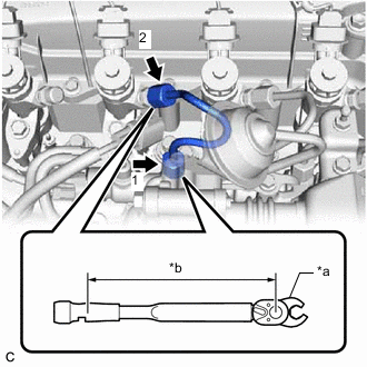
*a 17 mm Union Nut Wrench *b Torque Wrench Fulcrum Length Using a 17 mm union nut wrench, fully tighten the 2 union nuts in the order shown in the illustration.
- Torque:
- Specified tightening torque
- 28 N*m { 286 kgf*cm, 21 ft.*lbf }
Note
When fully tightening the union nuts, make sure to tighten from the common rail assembly side.
Tech Tips
-
Calculate the torque wrench reading when changing the fulcrum length of the torque wrench.
-
When using a 17 mm union nut wrench (fulcrum length of 30 mm (1.18 in.)) + torque wrench (fulcrum length of 180 mm (7.09 in.)): 24 N*m (245 kgf*cm, 18 ft.*lbf)
-
Install the vacuum transmitting pipe sub-assembly to the EGR cooler bracket with the bolt.
- Torque:
- 9.0 N*m { 92 kgf*cm, 80 in.*lbf }
-
Connect the vacuum hose to the No. 2 EGR valve assembly.
-
-
INSTALL NO. 2 INJECTION PIPE SUB-ASSEMBLY
Note
To prevent contamination by foreign matter, do not remove the plastic bag that is protecting the connector portion of the injector assembly and common rail assembly until immediately before installing the No. 2 injection pipe sub-assembly.
-
*a Correct *b Incorrect Temporarily install a new No. 2 injection pipe sub-assembly to the injector assembly and common rail assembly.
Note
-
When installing, the sealing surface of the No. 2 injection pipe sub-assembly should be fitted tightly against the injector assembly and common rail assembly.
-
When installing, do not tilt or angle the sealing surface of the No. 2 injection pipe sub-assembly.
-
When installing, tighten the union nut of the No. 2 injection pipe sub-assembly by hand until it cannot be turned any further.
-
-
Tighten the bolt of the No. 1 nozzle holder clamp.
- Torque:
- 19 N*m { 194 kgf*cm, 14 ft.*lbf }
-
*a 17 mm Union Nut Wrench *b Torque Wrench Fulcrum Length Using a 17 mm union nut wrench, fully tighten the 2 union nuts in the order shown in the illustration.
- Torque:
- Specified tightening torque
- 28 N*m { 286 kgf*cm, 21 ft.*lbf }
Note
When fully tightening the union nuts, make sure to tighten from the common rail assembly side.
Tech Tips
-
Calculate the torque wrench reading when changing the fulcrum length of the torque wrench.
-
When using a 17 mm union nut wrench (fulcrum length of 30 mm (1.18 in.)) + torque wrench (fulcrum length of 180 mm (7.09 in.)): 24 N*m (245 kgf*cm, 18 ft.*lbf)
-
-
INSTALL NO. 1 INJECTION PIPE SUB-ASSEMBLY
Note
To prevent contamination by foreign matter, do not remove the plastic bag that is protecting the connector portion of the injector assembly and common rail assembly until immediately before installing the No. 1 injection pipe sub-assembly.
-
*a Correct *b Incorrect Temporarily install a new No. 1 injection pipe sub-assembly to the injector assembly and common rail assembly.
Note
-
When installing, the sealing surface of the No. 1 injection pipe sub-assembly should be fitted tightly against the injector assembly and common rail assembly.
-
When installing, do not tilt or angle the sealing surface of the No. 1 injection pipe sub-assembly.
-
When installing, tighten the union nut of the No. 1 injection pipe sub-assembly by hand until it cannot be turned any further.
-
-
Tighten the bolt of the No. 1 nozzle holder clamp.
- Torque:
- 19 N*m { 194 kgf*cm, 14 ft.*lbf }
-
*a 17 mm Union Nut Wrench *b Torque Wrench Fulcrum Length Using a 17 mm union nut wrench, fully tighten the 2 union nuts in the order shown in the illustration.
- Torque:
- Specified tightening torque
- 28 N*m { 286 kgf*cm, 21 ft.*lbf }
Note
When fully tightening the union nuts, make sure to tighten from the common rail assembly side.
Tech Tips
-
Calculate the torque wrench reading when changing the fulcrum length of the torque wrench.
-
When using a 17 mm union nut wrench (fulcrum length of 30 mm (1.18 in.)) + torque wrench (fulcrum length of 180 mm (7.09 in.)): 24 N*m (245 kgf*cm, 18 ft.*lbf)
-
-
INSTALL NOZZLE LEAKAGE PIPE ASSEMBLY
-
INSTALL NO. 1 VACUUM SWITCHING VALVE ASSEMBLY
-
INSTALL NO. 1 GLOW PLUG CONNECTOR
-
INSTALL AIR CLEANER CAP SUB-ASSEMBLY
-
PERFORM INITIALIZATION AND REGISTRATION
-
BLEED AIR FROM FUEL SYSTEM
-
INSPECT FOR FUEL LEAK
-
INSTALL NO. 1 ENGINE COVER (w/ No. 1 Engine Cover)