FUEL INJECTOR(w/o Glow Plug Controller) INSTALLATION
CAUTION / NOTICE / HINT
Note
When replacing the injector assemblies (including exchanging the injector assemblies between the cylinders), it is necessary to replace the injection pipe sub-assemblies with new ones.
Tech Tips
After replacing any of the injector assemblies, perform both the "Injector Compensation" and the "Pilot Quantity Learning Values Reset" functions using the GTS.
PROCEDURE
-
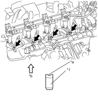
INSTALL INJECTION NOZZLE SEAT

*1 Injector Assembly *a Injector Nozzle *b Cylinder Head *c Cloth *d Sealing Surface Note
-
When installing, clean the sealing surface of the injector assembly, injection pipe sub-assembly and common rail assembly.
-
When replacing the injector assemblies, the injection pipe sub-assemblies must also be replaced.
-
Replace the injection pipe sub-assembly with a new one when the injection pipe sub-assembly has been removed and reinstalled more than 5 times.
-
Replace the injector assembly with one with the same part number and install it onto the cylinder.
-
Using a cloth and solvent, wipe away any carbon from the sealing surface of the injector assembly and injector installation hole as shown in the illustration.
Note
-
Do not damage the sealing surface.
-
Do not touch the injector nozzle.
-
-
Install 4 new injection nozzle seats onto the cylinder head.
-
-
INSTALL INJECTOR ASSEMBLY
-
Install the 4 injector assemblies onto the cylinder head.
Note
Fit the injector assemblies into the seats.
-
-
INSTALL NOZZLE HOLDER CLAMP SEAT
-
*1 Nozzle Holder Clamp Seat *a Concave *b Upper Install the 4 nozzle holder clamp seats onto the cylinder head.
Note
Install the nozzle holder clamp seats with the concave end facing up.
-
-
INSTALL NO. 1 NOZZLE HOLDER CLAMP
-
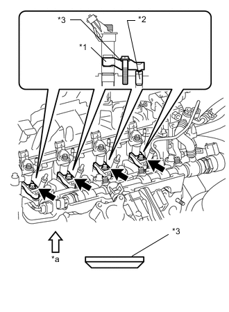
*1 No. 1 Nozzle Holder Clamp *2 Nozzle Holder Clamp Seat *3 Washer *a Upper Install the 4 nozzle holder clamps onto the injector assemblies.
-
Set the washer on the No. 1 nozzle holder clamp, as shown illustration.
Note
Install the washer in the correct direction.
-
Tighten the 4 No. 1 nozzle holder clamp bolts.
- Torque:
- 19 N*m { 194 kgf*cm, 14 ft.*lbf }
-
-
INSTALL NOZZLE LEAKAGE PIPE ASSEMBLY
-
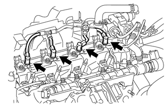
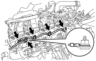
Install the nozzle leakage pipe assembly into each injector assembly.
-
Make sure the lock bush is at the top position.
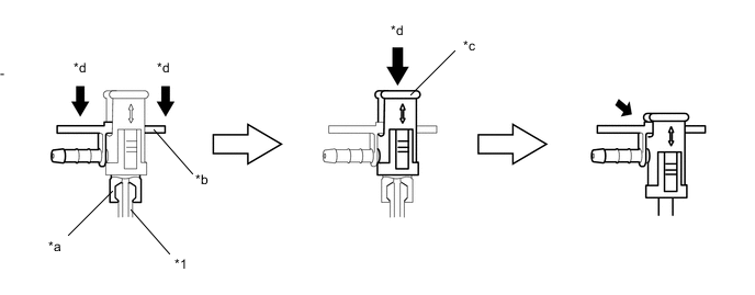
*1 Injector Assembly - - *a Rest Arm *b Return Plug *c Lock Bush *d Push -
Insert the rest arm into the injector assembly and push both sides of the return plug until the rest arm engages with the injector assembly as shown in the illustration.
Tech Tips
Push the nozzle leakage pipe assembly until it makes a click sound.
-
Push the lock bush until it fits with the return plug as shown in the illustration.
-
-
Connect the 4 connectors to the 4 injector assemblies.
-
-
INSTALL NO. 2 INTAKE MANIFOLD INSULATOR
-
Install the No. 2 intake manifold insulator.
-
-
INSTALL NO. 1 GLOW PLUG CONNECTOR
-
Install the No. 1 glow plug connector with the 4 nuts.
- Torque:
- 2.2 N*m { 22 kgf*cm, 19 in.*lbf }
-
Connect the glow terminal with the nut.
- Torque:
- 4.0 N*m { 41 kgf*cm, 35 in.*lbf }
Note
Install the glow terminal in the correct direction.
-
Install the 5 screw grommets.
Note
Push the screw grommet into the threaded portion of the glow plug by hand, and then turn it clockwise.
-
-
INSTALL NO. 1 INJECTION PIPE SUB-ASSEMBLY
-
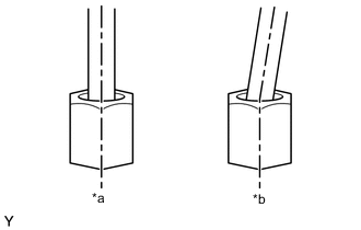
*a Correct *b Incorrect Temporarily install 4 new injection pipe sub-assemblies onto the injector assemblies and common rail assembly.
Note
Install the injection pipe sub-assembly and union nut vertically, not at a tilt.
-
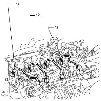
*1 No. 1 Injection Pipe Sub-assembly *2 No. 2 Injection Pipe Sub-assembly *3 No. 3 Injection Pipe Sub-assembly Using a 17 mm union nut wrench, tighten the injection pipe union nuts on the common rail assembly, and then tighten the union nuts on the injector assemblies.
- Torque:
- 28 N*m { 286 kgf*cm, 21 ft.*lbf }
Note
Use the torque value compensation formula to calculate the torque value for use when a torque wrench is combined with a tool such as a union nut wrench.
-
-
INSTALL NO. 2 INJECTION PIPE SUB-ASSEMBLY
Tech Tips
Perform the same procedure as for the No. 1 injection pipe sub-assembly.
-
INSTALL NO. 3 INJECTION PIPE SUB-ASSEMBLY
Tech Tips
Perform the same procedure as for the No. 1 injection pipe sub-assembly.
-
INSTALL NO. 1 EGR COOLER BRACKET
-
INSTALL EGR WITH COOLER PIPE ASSEMBLY
-
PERFORM REGISTRATION AND INITIALIZATION
-
BLEED AIR FROM FUEL SYSTEM
-
INSPECT FOR FUEL LEAK