CYLINDER BLOCK DISASSEMBLY

PROCEDURE
-
REMOVE NO. 1 VENTILATION CASE
Tech Tips
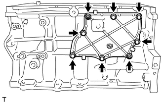
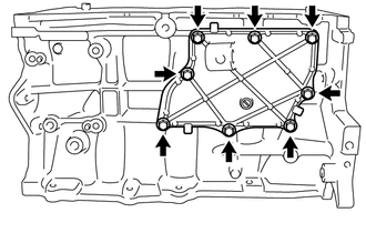
There are 2 installation types for the No. 1 ventilation case.
Depending on the installation type, the number of bolts, nuts and stud bolts used will vary.
-
Type A:
-
Remove the 6 bolts and 2 nuts.
-
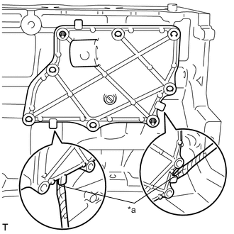
*a Protective Tape Remove the No. 1 ventilation case by prying between the No. 1 ventilation case and cylinder block sub-assembly with a screwdriver as shown in the illustration.
Note
Be careful not to damage the contact surfaces of the cylinder block sub-assembly and No. 1 ventilation case.
Tech Tips
Tape the screwdriver tip before use.
-
-
Type B:
-
Remove the 8 bolts.
-
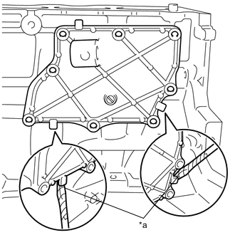
*a Protective Tape Remove the No. 1 ventilation case by prying between the No. 1 ventilation case and cylinder block sub-assembly with a screwdriver as shown in the illustration.
Note
Be careful not to damage the contact surfaces of the cylinder block sub-assembly and No. 1 ventilation case.
Tech Tips
Tape the screwdriver tip before use.
-
-
-
REMOVE PISTON SUB-ASSEMBLY WITH CONNECTING ROD
-
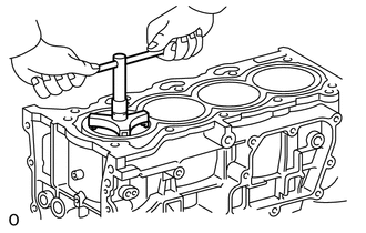
Using a ridge reamer, remove all of the carbon from the top of the cylinder.
-
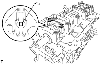
*a Matchmark Check that the matchmarks on the connecting rod and connecting rod cap are aligned to ensure correct reassembly.
Tech Tips
The matchmarks on the connecting rods and connecting rod caps are provided to ensure correct reassembly.
-
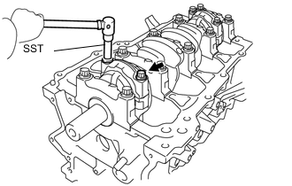
Using SST, uniformly loosen and remove the 2 connecting rod bolts.
- SST
- 09205-16011
-
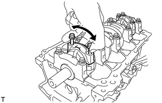
Using the 2 removed connecting rod bolts, remove the connecting rod cap and lower connecting rod bearing by wiggling the connecting rod cap back and forth.
Tech Tips
Keep the lower connecting rod bearing inserted in the connecting rod cap.
-
Push the piston, connecting rod and upper connecting rod bearing through the top of the cylinder block sub-assembly.
Tech Tips
-
Keep the connecting rod bearing, connecting rod and connecting rod cap together.
-
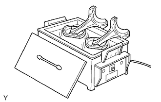
Arrange the removed parts in the correct order.
-
Be sure to arrange the removed piston and connecting rod in such a way that they can be reinstalled exactly as before.
-
-
-
REMOVE CONNECTING ROD BEARING
-
Remove the connecting rod bearings.
Tech Tips
Arrange the removed parts in the correct order.
-
-
REMOVE PISTON RING SET
-
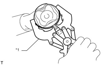
*1 Piston Ring Expander Using a piston ring expander, remove the 2 compression rings.
-
for 2-piece Type:
-
Remove the oil ring and oil ring expander by hand.
Tech Tips
Arrange the removed parts in the correct order.
-
-
for 3-piece Type:
-
Remove the oil ring expander, upper side rail and lower side rail by hand.
Tech Tips
Arrange the removed parts in the correct order.
-
-
-
REMOVE PISTON
-
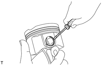
Using a screwdriver, pry out the 2 piston pin hole snap rings.
-
Gradually heat each piston to approximately 80 to 90°C (176 to 194°F).
-
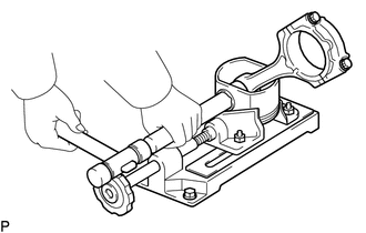
Using a plastic hammer and brass bar, lightly tap out the piston pin and remove the connecting rod.
Tech Tips
-
The piston and piston pin are a matched set.
-
Arrange the pistons, piston pins, rings, connecting rods and connecting rod bearings in the correct order.
-
-
-
REMOVE CRANKSHAFT
-
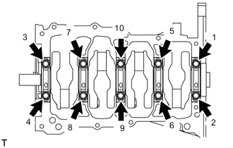
Uniformly loosen and remove the 10 crankshaft bearing cap set bolts in the order shown in the illustration.
-
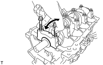
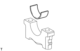
Using the 2 removed crankshaft bearing cap set bolts, remove the 5 crankshaft bearing caps and 5 lower crankshaft bearings.
Note
Insert the crankshaft bearing cap set bolts into the crankshaft bearing caps in turn. Ease the crankshaft bearing cap out by gently pulling it up while wiggling it back and forth, as shown in the illustration. Do not damage the contact surfaces of the crankshaft bearing cap and cylinder block sub-assembly.
Tech Tips
-
Keep the lower crankshaft bearing and crankshaft bearing cap together as a set.
-
Arrange the crankshaft bearing caps in the correct order.
-
-
Remove the crankshaft.
-
Check each crankshaft journal and crankshaft bearing for pitting and scratches.
If the journal or crankshaft bearing is damaged, replace the crankshaft bearings. If necessary, replace the crankshaft.
-
-
REMOVE UPPER CRANKSHAFT THRUST WASHER
-
Remove the 2 upper crankshaft thrust washers from the cylinder block sub-assembly.
-
-
REMOVE CRANKSHAFT BEARING
-
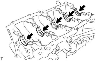
Remove the 5 upper crankshaft bearings from the cylinder block sub-assembly.
Tech Tips
Arrange the removed parts in the correct order.
-
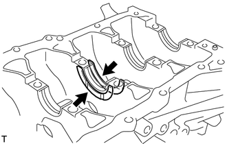
Remove the 5 lower crankshaft bearings from the 5 crankshaft bearing caps.
Tech Tips
Arrange the removed parts in the correct order.
-
-
REMOVE NO. 1 OIL NOZZLE SUB-ASSEMBLY
-
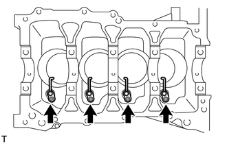
Using a 5 mm socket hexagon wrench, remove the 4 bolts and 4 No. 1 oil nozzle sub-assemblies.
-
-
CLEAN CYLINDER BLOCK
Note
If the cylinder block sub-assembly is washed at high temperatures, the cylinder liner will stick out beyond the cylinder block sub-assembly. Always wash the cylinder block sub-assembly at a temperature of 45°C (113°F) or less.