ENGINE UNIT REMOVAL

PROCEDURE
-
REMOVE VACUUM SURGE TANK
-
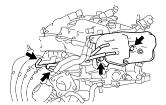
Slide the 2 clips and disconnect the 2 hoses.
-
Remove the 2 bolts and vacuum surge tank.
-
-
REMOVE INTAKE MANIFOLD
-
Remove the 2 bolts and disconnect the air tube from the cylinder head cover sub-assembly.
-
Slide the 2 clamps and disconnect the 2 water by-pass hoses.
-
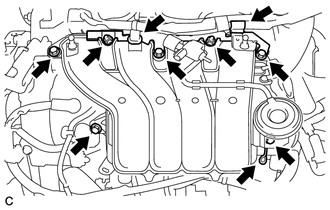
Disconnect the 2 clamps.
-
Slide the clamp and disconnect the ventilation hose from the intake manifold.
-
Remove the 4 bolts, 2 nuts and intake manifold and intake manifold stay.
-
Remove the No. 1 intake manifold to head gasket from the intake manifold.
-
-
DISCONNECT FUEL TUBE SUB-ASSEMBLY
-
REMOVE FUEL DELIVERY PIPE SUB-ASSEMBLY
-
REMOVE NO. 1 DELIVERY PIPE SPACER
-
REMOVE FUEL INJECTOR ASSEMBLY
-
REMOVE IGNITION COIL ASSEMBLY
-

*1 Engine Head Cover *2 Spark Plug Tube *3 Plug Cap Remove the 4 bolts and 4 ignition coil assemblies.
Note
When removing each ignition coil assembly, do not damage the plug cap on the engine head cover opening or the upper edge of the spark plug tube.
-
-
REMOVE ENGINE OIL LEVEL DIPSTICK GUIDE
-
Remove the engine oil level dipstick.
-
Remove the bolt and engine oil level dipstick guide.
-
Remove the O-ring from the engine oil level dipstick guide.
-
-
REMOVE NO. 1 EXHAUST MANIFOLD HEAT INSULATOR
-
REMOVE MANIFOLD STAY
-
REMOVE EXHAUST MANIFOLD
-
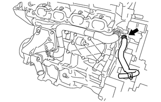
REMOVE VENTILATION HOSE
-

Slide the clip and remove the ventilation hose from the ventilation valve.
-
-
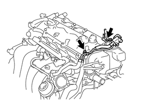
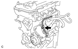
DISCONNECT NO. 3 WATER BY-PASS HOSE
-

Slide the clip and disconnect the No. 3 water by-pass hose from the water inlet housing.
-
-
REMOVE NO. 1 WATER BY-PASS PIPE
-
Remove the 2 bolts and No. 1 water by-pass pipe.
-
-
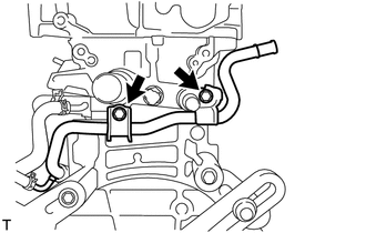
DISCONNECT WATER BY-PASS HOSE
-
Slide the clip and disconnect the water by-pass hose from the cylinder head sub-assembly.
-
-
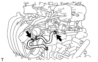
DISCONNECT WATER INLET HOSE
-

Slide the 2 clamps and disconnect the water inlet hose.
-
-
REMOVE WATER INLET
-
REMOVE THERMOSTAT