ENGINE ASSEMBLY INSTALLATION

PROCEDURE
-
INSTALL ENGINE HANGER
-
REMOVE ENGINE FROM ENGINE STAND
-
Using a chain block and engine sling device, secure the engine assembly.
Note
-
Adjust the angle of the sling device carefully to prevent the engine assembly or engine hangers from deforming or becoming damaged.
-
Servicing an engine assembly while it is hanging is dangerous. This can be done only when installing/removing the engine assembly to/from an engine stand.
-
-
Remove the engine assembly from the engine stand.
-
-
INSTALL DRIVE PLATE AND RING GEAR SUB-ASSEMBLY
-
Gently place the engine assembly on wooden blocks or equivalent.
CAUTION:
This step should be done while hanging the engine assembly using the engine hangers and a chain block.
-
Install the drive plate and ring gear sub-assembly.
-
-
INSTALL CONTINUOUSLY VARIABLE TRANSAXLE ASSEMBLY
-
INSTALL STARTER ASSEMBLY
-
INSTALL FLYWHEEL HOUSING SIDE COVER
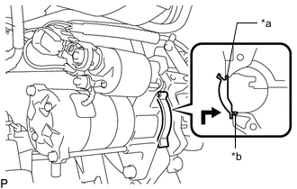
*a Protruding Portion *b Claw
-
Insert the protruding portion into the end of the cylinder block sub-assembly and while pushing it along the cylinder block sub-assembly, fit the claw into the stiffening crankcase assembly.
Note
-
Make sure that the claw makes a click sound, indicating that it fits tightly.
-
Replace the flywheel housing side cover with a new one if the claw does not fit tightly or is deformed.
-
-
-
INSTALL ENGINE WIRE
-
Install the engine wire to the engine assembly with transaxle.
-
-
CONNECT NO. 5 WATER BY-PASS HOSE
-
Connect the No. 5 water by-pass hose to the No. 1 water by-pass pipe.
-
-
REMOVE ENGINE HANGER
-
Remove the 2 bolts and No. 1 and No. 2 engine hangers.
-
-
INSTALL WIRE HARNESS CLAMP BRACKET
-
Install the wire harness clamp bracket with the bolt.
- Torque:
- 39 N*m { 398 kgf*cm, 29 ft.*lbf }
-
Connect the clamp and wire harness to the wire harness clamp bracket.
-
-
INSTALL ENGINE MOUNTING INSULATOR SUB-ASSEMBLY RH
Tech Tips
Perform this procedure only when replacement of the engine mounting insulator sub-assembly RH is necessary.
-
Install the engine mounting insulator sub-assembly RH with the 3 bolts.
- Torque:
- 95 N*m { 969 kgf*cm, 70 ft.*lbf }
-
Install the cooler pipe clamp bracket to the engine mounting insulator sub-assembly RH with the bolt.
- Torque:
- 9.8 N*m { 100 kgf*cm, 87 in.*lbf }
-
Connect the cooler pipe clamp to the engine mounting insulator sub-assembly RH.
-
Install the radiator reservoir tank with the 2 bolts.
- Torque:
- 5.0 N*m { 51 kgf*cm, 44 in.*lbf }
-
-
INSTALL ENGINE MOUNTING INSULATOR LH
Tech Tips
Perform this procedure only when replacement of the engine mounting insulator LH is necessary.
-
Install the engine mounting insulator LH with the 4 bolts.
- Torque:
- 95 N*m { 969 kgf*cm, 70 ft.*lbf }
-
-
TEMPORARILY TIGHTEN REAR ENGINE MOUNTING INSULATOR
Tech Tips
Perform this procedure only when replacement of the rear engine mounting insulator is necessary.
-
Temporarily install the rear engine mounting insulator to the rear engine mounting bracket with the through bolt.
-
-
TEMPORARILY TIGHTEN FRONT ENGINE MOUNTING INSULATOR
Tech Tips
Perform this procedure only when replacement of the front engine mounting insulator is necessary.
-
Temporarily install the front engine mounting insulator to the front engine mounting bracket with the through bolt and nut.
-
-
INSTALL ENGINE ASSEMBLY WITH TRANSAXLE
-
Set the engine assembly with transaxle on an engine lifter.
Note
Place height adjustment attachments and plate lift attachments under the engine assembly with transaxle.
-
Operate the engine lifter and lift the engine assembly with transaxle to the position where the engine mounting insulator sub-assembly RH and engine mounting insulator LH can be installed.
CAUTION:
Do not raise the engine assembly with transaxle more than necessary. If the engine assembly with transaxle is raised excessively, the vehicle may also be lifted up.
Note
-
Make sure that the engine assembly with transaxle is clear of all wiring and hoses.
-
While raising the engine assembly with transaxle into the vehicle, do not allow it to contact the vehicle.
-
-
Install the engine mounting insulator LH with the through bolt and nut.
- Torque:
- 56 N*m { 571 kgf*cm, 41 ft.*lbf }
Tech Tips
Tighten the through bolt while holding the nut.
-
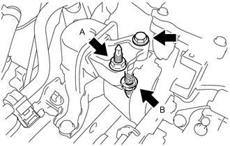
Install the engine mounting insulator sub-assembly RH with the bolt and 2 nuts.
- Torque:
- Nut A
- 95 N*m { 969 kgf*cm, 70 ft.*lbf }
- Nut B
- 52 N*m { 530 kgf*cm, 38 ft.*lbf }
- Bolt
- 95 N*m { 969 kgf*cm, 70 ft.*lbf }
-
Install the front crossmember sub-assembly with the 4 bolts.
- Torque:
- 99 N*m { 1010 kgf*cm, 73 ft.*lbf }
-
Connect the front engine mounting insulator sub-assembly to the front crossmember sub-assembly with the 2 bolts.
- Torque:
- 95 N*m { 969 kgf*cm, 70 ft.*lbf }
-
-
INSTALL FRONT SUSPENSION CROSSMEMBER SUB-ASSEMBLY
-
INSTALL FRONT SUSPENSION MEMBER REAR BRACE LH
-
INSTALL FRONT SUSPENSION MEMBER REAR BRACE RH
Tech Tips
Perform the same procedure as for the LH side.
-
INSTALL FRONT SUSPENSION MEMBER REINFORCEMENT LH
-
INSTALL FRONT SUSPENSION MEMBER REINFORCEMENT RH
-
INSTALL FRONT ENGINE MOUNTING BRACKET LOWER REINFORCEMENT
-
FULLY INSTALL REAR ENGINE MOUNTING INSULATOR
-
Fully install the rear engine mounting insulator with the through bolt.
- Torque:
- 95 N*m { 969 kgf*cm, 70 ft.*lbf }
-
-
FULLY INSTALL FRONT ENGINE MOUNTING INSULATOR
-
Fully install the front engine mounting insulator with the nut and through bolt.
- Torque:
- 85 N*m { 867 kgf*cm, 63 ft.*lbf }
Tech Tips
Tighten the through bolt while holding the nut.
-
-
INSTALL DRIVE PLATE AND TORQUE CONVERTER ASSEMBLY SETTING BOLT
-
INSTALL FLYWHEEL HOUSING UNDER COVER
-
Install the flywheel housing under cover.
-
-
INSTALL DRIVE SHAFT ASSEMBLY
-
INSTALL FRONT EXHAUST PIPE ASSEMBLY (TWC: Front and Rear Catalyst)
-
CONNECT NO. 1 STEERING COLUMN HOLE COVER SUB-ASSEMBLY
-
CONNECT NO. 2 STEERING INTERMEDIATE SHAFT ASSEMBLY
-
INSTALL COLUMN HOLE COVER SILENCER SHEET
-
CONNECT WIRE HARNESS
-
Install the No. 3 engine wire to the CVT with the bolt and clamp.
- Torque:
- 12.5 N*m { 127 kgf*cm, 9 ft.*lbf }
-
Connect the 3 wire harness connectors and wire harness to the engine room junction block and engage the 2 claws.
-
Install the 2 nuts to the engine room relay block and junction block assembly.
- Torque:
- 8.5 N*m { 87 kgf*cm, 75 in.*lbf }
-
Install the No. 1 engine room relay block cover to the engine room relay block and junction block assembly.
-
Connect the wire harness clamp.
-
Connect the ECM connector and lower the lever.
-
-
INSTALL COMPRESSOR ASEEMBLY WITH PULLEY
-
INSTALL SUCTION HOSE SUB-ASSEMBLY
-
INSTALL DISCHARGE HOSE SUB-ASSEMBLY
-
INSTALL GENERATOR ASSEMBLY
-
INSTALL V-RIBBED BELT
-
ADJUST V-RIBBED BELT
-
INSPECT V-RIBBED BELT
-
CONNECT FUEL TUBE SUB-ASSEMBLY
-
Connect the fuel tube connector and fuel pipe.
Note
Align the fuel tube connector with the fuel pipe, then push the fuel tube connector in until the retainer makes a "click" sound.
If the connection is tight, apply a small amount of engine oil to the tip of the fuel pipe.
After connecting, pull the fuel pipe and fuel tube connector to make sure that they are securely connected.
-
Engage the claw and install the No. 1 fuel pipe clamp.
-
-
CONNECT INLET HEATER WATER HOSE
-
Connect the inlet heater water hose to the air conditioner unit assembly and slide the clip to secure it.
-
-
CONNECT OUTLET HEATER WATER HOSE
-
Connect the outlet heater water hose to the No. 1 water by-pass pipe and slide the clip to secure it.
-
Connect the outlet heater water hose to the air conditioner unit assembly and slide the clip to secure it.
-
-
CONNECT UNION TO VACUUM TUBE HOSE
-
Connect the union to vacuum tube hose to the air tube and slide the clip to secure it.
-
-
CONNECT NO. 1 FUEL VAPOR FEED HOSE
-
Connect the No. 1 fuel vapor feed hose to the vacuum switching valve assembly and slide the clip to secure it.
-
-
INSTALL TRANSMISSION CONTROL CABLE ASSEMBLY
-
Install the transmission control cable assembly to the rear engine mounting insulator with the bolt.
- Torque:
- 5.0 N*m { 51 kgf*cm, 44 in.*lbf }
-
Install the transmission control cable assembly to the transmission control cable bracket with a new clip.
-
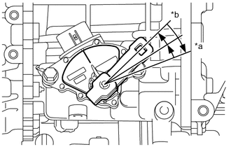
*a P Position *b N Position Turn the lever clockwise until it stops, then turn it counterclockwise 2 notches.
-
Install the transmission control cable assembly to the control shaft lever with the nut.
- Torque:
- 12 N*m { 122 kgf*cm, 9 ft.*lbf }
-
-
CONNECT NO. 2 RADIATOR HOSE
-
Connect the No. 2 radiator hose to the water inlet and slide the clip to secure it.
-
-
CONNECT NO. 1 RADIATOR HOSE
-
Connect the No. 1 radiator hose to the cylinder head sub-assembly and slide the clip to secure it.
-
Connect breather plug hose to the clamp.
-
-
INSTALL BATTERY CARRIER ASSEMBLY
-
Install the battery carrier assembly with the 4 bolts.
- Torque:
- 18.5 N*m { 189 kgf*cm, 14 ft.*lbf }
-
Connect the radiator pipe with the 2 bolts.
- Torque:
- 18.5 N*m { 189 kgf*cm, 14 ft.*lbf }
-
Connect the 2 wire harness clamps.
-
-
INSTALL BATTERY
-
Install the battery tray.
-
Install the battery.
-
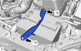
*a Bolt *b Nut Install the battery clamp sub-assembly with the bolt and nut.
- Torque:
- Bolt
- 16.5 N*m { 168 kgf*cm, 12 ft.*lbf }
- Nut
- 3.5 N*m { 36 kgf*cm, 31 in.*lbf }
-
Connect the cable to the positive (+) battery terminal.
- Torque:
- 5.4 N*m { 55 kgf*cm, 48 in.*lbf }
-
-
INSTALL AIR CLEANER CASE SUB-ASSEMBLY
-
Install the air cleaner case sub-assembly with the 3 bolts.
- Torque:
- 7.0 N*m { 71 kgf*cm, 62 in.*lbf }
-
Install the wire harness clamp to the air cleaner case.
-
Install the air cleaner filter element sub-assembly.
-
-
INSTALL AIR CLEANER CAP SUB-ASSEMBLY
-
CONNECT CABLE TO NEGATIVE BATTERY TERMINAL
-
Connect the negative (-) cable to the negative (-) battery terminal.
- Torque:
- 5.4 N*m { 55 kgf*cm, 48 in.*lbf }
Note
When disconnecting the cable, some systems need to be initialized after the cable is reconnected.
-
-
ADD ENGINE OIL
-
ADD ENGINE COOLANT
-
ADD CONTINUOUSLY VARIABLE TRANSAXLE FLUID
-
INSPECT ENGINE OIL LEVEL
-
INSPECT SHIFT LEVER POSITION
-
ADJUST SHIFT LEVER POSITION
-
INSPECT FOR FUEL LEAK
-
INSPECT FOR ENGINE COOLANT LEAK
-
INSPECT FOR OIL LEAK
-
INSPECT FOR EXHAUST GAS LEAK
-
INSTALL REAR ENGINE UNDER COVER LH
-
Install the rear engine under cover LH with the 5 clips.
-
-
INSTALL REAR ENGINE UNDER COVER RH
-
Install the rear engine under cover RH with the 5 clips.
-
-
INSTALL NO. 2 ENGINE UNDER COVER
-
Install the No. 2 engine under cover with the 5 clips.
-
-
INSTALL NO. 1 ENGINE UNDER COVER
-
Install the No. 1 engine under cover with the 2 clips and 5 bolts.
-
-
INSTALL FRONT LOWER BUMPER ABSORBER
-
Install the front lower bumper absorber with the 4 screws and 8 bolts.
-
-
CHARGE AIR CONDITIONING SYSTEM WITH REFRIGERANT (for HFC-134a(R134a))
-
CHARGE AIR CONDITIONING SYSTEM WITH REFRIGERANT (for HFO-1234yf(R1234yf))
-
WARM UP ENGINE (for HFC-134a(R134a))
-
WARM UP ENGINE (for HFO-1234yf(R1234yf))
-
INSPECT FOR REFRIGERANT LEAK (for HFC-134a(R134a))
-
INSPECT FOR REFRIGERANT LEAK (for HFO-1234yf(R1234yf))
-
INSTALL FRONT WHEELS
- Torque:
- 103 N*m { 1050 kgf*cm, 76 ft.*lbf }
-
INSPECT IGNITION TIMING
-
INSPECT ENGINE IDLE SPEED
-
INSPECT CO/HC
-
ADJUST FRONT WHEEL ALIGNMENT
-
INSTALL NO. 2 CYLINDER HEAD COVER
-
Engage the 4 clips to install the No. 2 cylinder head cover.
Note
-
Be sure to engage the clips securely.
-
Do not apply excessive force or hit the No. 2 cylinder head cover to engage the clips. This may cause the No. 2 cylinder head cover to break.
-
-
-
INSPECT FOR SPEED SENSOR SIGNAL
w/ VSC: Click here
w/o VSC: Click here