REAR CRANKSHAFT OIL SEAL REMOVAL

PROCEDURE
-
REMOVE CONTINUOUSLY VARIABLE TRANSAXLE ASSEMBLY
-
REMOVE DRIVE PLATE AND RING GEAR SUB-ASSEMBLY
-
Using height adjustment attachments and plate lift attachments, place the engine assembly on a flat, level surface.
Note
-
Using height adjustment attachments and plate lift attachments, place the engine assembly horizontally.
-
To prevent the oil pan sub-assembly from deforming, do not place any attachments under the oil pan sub-assembly of the engine assembly.
-
Using an engine sling device and engine lift, secure the engine assembly before servicing.
-
-
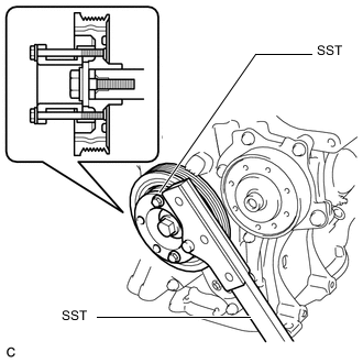
Using SST, hold the crankshaft.
for 86 mm (3.39 in.) Bolt Pitch Type:
- SST
- 09213-58014 ( 91551-80840 )
- 09330-00021
for 64 mm (2.52 in.) Bolt Pitch Type:
- SST
- 09213-54015
Tech Tips
For the 64 mm (2.52 in.) bolt pitch type, the part number of the installation bolt for SST (crankshaft pulley holding tool) is 91551-00850 (quantity: 2).
-
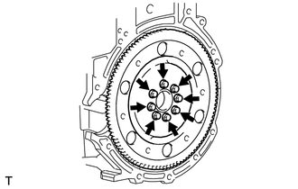
Remove the 8 bolts, the rear drive plate spacer, the drive plate and ring gear sub-assembly and the front drive plate spacer.
-
-
REMOVE REAR ENGINE OIL SEAL
-
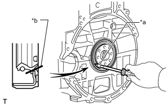
*a Protective Tape *b Cut Position Using a knife, cut off the rear engine oil seal lip.
-
Using a screwdriver with its tip wrapped with protective tape, pry out the rear engine oil seal.
Note
After removing, check the crankshaft and cylinder block sub-assembly for damage. If damaged, smooth the surface with 400-grit sandpaper.
-