ENGINE ASSEMBLY INSTALLATION
CAUTION / NOTICE / HINT
CAUTION:
As the engine assembly with transaxle assembly is extremely heavy, the engine lifter may suddenly drop if the instructions listed in the repair manual are not followed. Therefore, always follow the instructions listed in the repair manual when performing this procedure.
PROCEDURE
-
INSTALL ENGINE MOUNTING INSULATOR LH
Tech Tips
Perform this procedure only when replacement of the engine mounting insulator LH is necessary.
-
Install the engine mounting insulator LH to the vehicle body with the 4 bolts.
- Torque:
- 95 N*m { 969 kgf*cm, 70 ft.*lbf }
-
-
TEMPORARILY INSTALL FRONT ENGINE MOUNTING INSULATOR
-
Temporarily install the front engine mounting insulator with the bolt and nut.
-
-
TEMPORARILY INSTALL REAR ENGINE MOUNTING INSULATOR
-
Temporarily install the rear engine mounting insulator with the bolt.
-
-
REMOVE ENGINE FROM ENGINE STAND
Note
-
Pay attention to the angle of the sling device as the engine assembly or engine hangers may be damaged or deformed if the angle is incorrect.
-
With the exception of installing the engine assembly to an engine stand or removing the engine assembly from an engine stand, do not perform any work on the engine assembly while it is suspended, as doing so is dangerous.
-
Install a sling device and chain block to the engine assembly and hang the engine assembly.
-
Remove the engine assembly from the engine stand.
-
-
INSTALL MANUAL TRANSAXLE ASSEMBLY
-
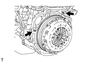
Make sure that the dowel pins are not loose, bent, damaged or scratched.
-
Align the input shaft with the clutch disc assembly and install the engine assembly to the transaxle.
-
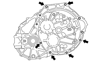
Temporarily install the engine assembly with the 6 bolts.
Note
-
Be extremely careful that the vehicle body, clutch pipe line and radiator cooling fan do not interfere with the manual transaxle assembly when installing the manual transaxle assembly.
-
Make sure that the wire harness or similar items are not pinched between the contact surfaces.
-
Do not forcibly pry on the manual transaxle assembly when installing it to the engine assembly.
-
Before tightening the bolts, insert the dowel pins into the dowel holes securely so that the end face of the transaxle assembly fits close against the engine assembly.
-
Do not apply excessive force to the manual transaxle assembly as this will break the input shaft.
-
Make sure that the contact surfaces of the engine assembly and manual transaxle assembly are flat against each other before tightening the bolts.
-
-
-
TEMPORARILY INSTALL NO. 2 MANIFOLD STAY
-
TEMPORARILY INSTALL STARTER ASSEMBLY
-
TIGHTEN ENGINE AND TRANSAXLE CONNECTING BOLT
-
INSTALL NO. 1 CLUTCH HOUSING COVER
-
INSTALL NO. 1 AIR TUBE ASSEMBLY
-
Install the No. 1 air tube assembly to the manual transaxle assembly with the 2 bolts.
- Torque:
- 20 N*m { 204 kgf*cm, 15 ft.*lbf }
-
Connect the No. 4 water by-pass hose to the EGR cooler assembly.
-
Connect the compressor outlet elbow to the turbocharger sub-assembly.
-
-
INSTALL ENGINE WIRE
-
Connect the connectors, attach the clamps and install the engine wire to the engine assembly with the bracket bolts.
-
-
INSTALL ENGINE ASSEMBLY WITH TRANSAXLE
-
Set the engine assembly with transaxle on the engine lifter.
Note
Place height adjustment attachments and plate lift attachments under the engine assembly with transaxle.
-
Operate the engine lifter and lift the engine assembly with transaxle to the position where the engine mounting insulator LH and engine mounting insulator sub-assembly RH can be installed.
CAUTION:
Do not raise the engine more than necessary. If the engine is raised excessively, the vehicle may also be lifted up.
Note
While raising the engine assembly with transaxle into the vehicle, do not allow it to contact the vehicle.
-
Install the engine mounting insulator LH with the bolt and nut.
- Torque:
- 56 N*m { 571 kgf*cm, 41 ft.*lbf }
Tech Tips
When tightening the through bolt, keep the nut from rotating.
-
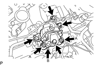
Install the engine mounting insulator sub-assembly RH with the 4 bolts and 3 nuts.
- Torque:
- Bolt and Nut (A)
- 95 N*m { 969 kgf*cm, 70 ft.*lbf }
- Nut (B)
- 52 N*m { 530 kgf*cm, 38 ft.*lbf }
-
Attach the 2 clamps and connect the suction pipe sub-assembly.
-
Attach the clamp and connect the air conditioner tube and accessory assembly.
-
Install the front crossmember sub-assembly with the 4 bolts.
- Torque:
- 99 N*m { 1010 kgf*cm, 73 ft.*lbf }
-
Connect the front engine mounting insulator to the front crossmember sub-assembly with the 2 bolts.
- Torque:
- 95 N*m { 969 kgf*cm, 70 ft.*lbf }
-
-
INSTALL FRONT SUSPENSION CROSSMEMBER SUB-ASSEMBLY
-
INSTALL FRONT SUSPENSION MEMBER REAR BRACE LH
-
INSTALL FRONT SUSPENSION MEMBER REAR BRACE RH
Tech Tips
Perform the same procedure as for the LH side.
-
INSTALL FRONT SUSPENSION MEMBER REINFORCEMENT LH
-
INSTALL FRONT SUSPENSION MEMBER REINFORCEMENT RH
-
INSTALL FRONT ENGINE MOUNTING BRACKET LOWER REINFORCEMENT (w/ Reinforcement)
-
INSTALL REAR ENGINE MOUNTING INSULATOR
-
Fully install the rear engine mounting insulator with the bolt.
- Torque:
- 95 N*m { 969 kgf*cm, 70 ft.*lbf }
-
-
INSTALL FRONT ENGINE MOUNTING INSULATOR
-
Fully install the front engine mounting insulator with the nut and bolt.
- Torque:
- 145 N*m { 1479 kgf*cm, 107 ft.*lbf }
Tech Tips
Tighten the through bolt while holding the nut.
-
-
INSTALL FRONT DRIVE SHAFT ASSEMBLY
-
INSTALL NO. 1 STEERING COLUMN HOLE COVER SUB-ASSEMBLY
-
CONNECT NO. 2 STEERING INTERMEDIATE SHAFT ASSEMBLY
-
INSTALL COLUMN HOLE COVER SILENCER SHEET
-
CONNECT CLUTCH RELEASE CYLINDER ASSEMBLY
-
CONNECT TRANSMISSION CONTROL CABLE ASSEMBLY
-
INSTALL AIR CLEANER BRACKET
-
Install the air cleaner bracket with the 3 bolts.
- Torque:
- 7.0 N*m { 71 kgf*cm, 62 in.*lbf }
-
-
INSTALL GLOW PLUG RELAY ASSEMBLY
-
Install the glow plug relay assembly to the fuel filter support with the bolt.
- Torque:
- 17.5 N*m { 178 kgf*cm, 13 ft.*lbf }
-
Connect the wire harness clamp to the fuel filter support.
-
-
INSTALL FUEL FILTER SUPPORT
-
Install the fuel filter support with the 3 bolts.
- Torque:
- 17.5 N*m { 178 kgf*cm, 13 ft.*lbf }
-
Attach the clamp to connect the wire harness.
-
Attach the 2 clamps and connect the engine wire.
-
Connect the connector.
-
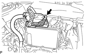
Connect the ECM connector and lower the lever.
Note
-
When connecting the ECM connector, make sure that dirt, water or other foreign matter is not stuck between the ECM connector and ECM.
-
Make sure that the lever is securely locked.
-
-
-
INSTALL FUEL FILTER ASSEMBLY
-
w/ Fuel Heater Relay:
-
w/o Fuel Heater Relay:
-
-
INSTALL NO. 1 FUEL FILTER PROTECTOR
-
w/ Fuel Heater Relay:
-
w/o Fuel Heater Relay:
-
-
CONNECT ENGINE WIRE
-
Connect the ground cable with the bolt.
- Torque:
- 12.5 N*m { 127 kgf*cm, 9 ft.*lbf }
-
Connect the 2 connectors and engine wire, attach the 2 claws to the No. 1 engine room relay block and install the 2 nuts.
- Torque:
- 8.4 N*m { 86 kgf*cm, 74 in.*lbf }
-
Install the No. 1 engine room relay block cover.
-
-
CONNECT OUTLET HEATER WATER HOSE
-
Connect the outlet heater water hose to the No. 1 air tube assembly, and slide the clamp to secure the hose.
-
-
CONNECT WATER HOSE SUB-ASSEMBLY
-
Connect the water hose sub-assembly to the No. 1 air tube assembly, and slide the clamp to secure the hose.
-
-
CONNECT FUEL HOSE
-
Connect the fuel hose to the fuel feed pipe sub-assembly.
-
-
CONNECT NO. 2 FUEL HOSE
-
Connect the No. 2 fuel hose to the fuel feed pipe sub-assembly.
-
-
CONNECT VACUUM HOSE
-
Connect the vacuum hose to the No. 2 vacuum hose assembly, and slide the clamp to secure the hose.
-
-
INSTALL RADIATOR HOSE SUB-ASSEMBLY
-
Install the radiator hose sub-assembly to the water outlet.
-
Connect the radiator hose sub-assembly, and slide the clamp to secure the clamp hose.
-
-
INSTALL WATER BY-PASS HOSE ASSEMBLY
-
Connect the water by-pass hose assembly to the water by-pass pipe.
-
Connect the water by-pass hose assembly to the No. 1 air tube assembly, and slide the clamp to secure the hose.
-
-
INSTALL RADIATOR RESERVE TANK ASSEMBLY
-
Install the radiator reserve tank assembly with the 2 bolts.
- Torque:
- 5.0 N*m { 51 kgf*cm, 44 in.*lbf }
-
Connect the No. 2 water by-pass hose assembly to the radiator reserve tank assembly, and slide the clamp to secure the hose.
-
Connect the water by-pass hose assembly to the radiator reserve tank assembly, and slide the clamp to secure the hose.
-
-
INSTALL AIR CLEANER CASE SUB-ASSEMBLY
-
INSTALL AIR CLEANER CAP SUB-ASSEMBLY WITH AIR CLEANER HOSE ASSEMBLY
-
CONNECT DISCHARGE HOSE SUB-ASSEMBLY (w/ Air Conditioning System)
-
CONNECT SUCTION HOSE SUB-ASSEMBLY (w/ Air Conditioning System)
-
INSTALL BATTERY CARRIER
-
Install the battery carrier with the 4 bolts.
- Torque:
- 18.5 N*m { 189 kgf*cm, 14 ft.*lbf }
-
Engage the 2 clamps.
-
-
INSTALL BATTERY
-
Install the battery and battery tray.
-
Install the battery.
-
Install the battery insulator to the battery.
-
Install the battery clamp sub-assembly with the battery clamp bolt, bolt and nut.
- Torque:
- Nut
- 3.5 N*m { 36 kgf*cm, 31 in.*lbf }
- Bolt
- 16.5 N*m { 168 kgf*cm, 12 ft.*lbf }
-
Connect the cable to the positive (+) battery terminal and tighten the nut.
- Torque:
- 5.4 N*m { 55 kgf*cm, 48 in.*lbf }
-
-
INSTALL FRONT LOWER BUMPER ABSORBER
-
Install the 2 hooks of the front lower bumper absorber into the installation holes in the body to install the front lower bumper absorber.
-
Install the front lower bumper absorber with the 4 bolts.
-
-
INSTALL RADIATOR ASSEMBLY
-
INSTALL FRONT EXHAUST PIPE ASSEMBLY
-
INSTALL FRONT CENTER FLOOR BRACE SUB-ASSEMBLY
-
ADD MANUAL TRANSAXLE OIL
-
ADD ENGINE OIL
-
INSTALL OUTER COWL TOP PANEL
-
for LHD:
-
for RHD
-
-
INSTALL WINDSHIELD WIPER MOTOR ASSEMBLY
-
PERFORM REGISTRATION
-
INSPECT FOR ENGINE OIL LEAK
-
INSPECT FOR FUEL LEAK
-
INSPECT FOR EXHAUST GAS LEAK
-
INSTALL REAR ENGINE UNDER COVER RH
-
Install the rear engine under cover RH with the 5 clips.
-
-
INSTALL REAR ENGINE UNDER COVER LH
-
Install the rear engine under cover LH with the 5 clips.
-
-
INSTALL NO. 2 ENGINE UNDER COVER
-
Install the No. 2 engine under cover with the 4 clips.
-
-
INSTALL CENTER NO. 4 ENGINE UNDER COVER (w/ Cover)
-
Install the center No. 4 engine under cover with the 2 clips.
-
-
INSTALL NO. 1 ENGINE COVER
-
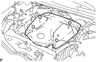
*a Installation Points Attach the 4 clips in the sequence shown in the illustration to install the No. 1 engine cover.
Tech Tips
When attaching the clips, press the protrusions on the top of the No. 1 engine cover at the clip installation points.
-
-
INSPECT ENGINE IDLE SPEED
-
INSPECT MAXIMUM ENGINE SPEED
-
INSPECT AND ADJUST FRONT WHEEL ALIGNMENT
-
CHECK SPEED SENSOR SIGNAL