CYLINDER BLOCK INSPECTION

PROCEDURE
-
INSPECT CONNECTING ROD THRUST CLEARANCE
-
Install the connecting rod cap.
-
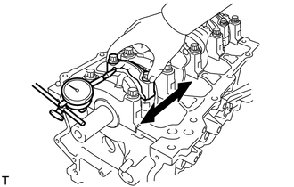
Using a dial indicator, measure the thrust clearance while moving the connecting rod cap back and forth.
Standard thrust clearance 0.160 to 0.342 mm (0.00630 to 0.0135 in.) Maximum thrust clearance 0.342 mm (0.0135 in.) If the thrust clearance is greater than the maximum, replace the connecting rod as necessary. If necessary, replace the crankshaft.
-
-
INSPECT CONNECTING ROD OIL CLEARANCE
-
Clean the crank pin and connecting rod bearing.
-
Check the crank pin and connecting rod bearing for pitting and scratches.
-
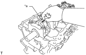
*a Plastigage Lay a strip of Plastigage on the crank pin.
-
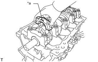
*a Front Mark Check that the front mark of the connecting rod cap is facing forward.
-
Install the connecting rod cap.
Note
Do not turn the crankshaft.
-
Remove the connecting rod cap.
-
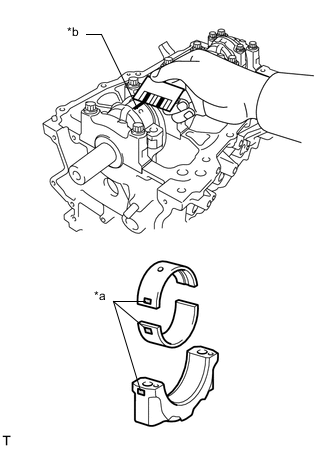
*a 1, 2 or 3 Mark *b Plastigage Measure the Plastigage at its widest point.
Standard oil clearance 0.014 to 0.038 mm (0.000551 to 0.00150 in.) Maximum oil clearance 0.070 mm (0.00276 in.) If the oil clearance is greater than the maximum, replace the connecting rod bearings. If necessary, replace the crankshaft.
Note
Remove the Plastigage completely after the measurement.
Tech Tips
If replacing a connecting rod bearing, replace it with one that has the same number as its respective connecting rod cap. Each connecting rod bearing standard thickness is indicated by a 1, 2, or 3 mark on its surface.
Standard Connecting Rod Large End Bore Diameter Mark Specified Condition 1 47.000 to 47.008 mm (1.85039 to 1.85070 in.) 2 47.009 to 47.016 mm (1.85074 to 1.85102 in.) 3 47.017 to 47.024 mm (1.85106 to 1.85133 in.) Standard Connecting Rod Bearing Thickness Mark Specified Condition 1 1.489 to 1.493 mm (0.058621 to 0.058779 in.) 2 1.494 to 1.497 mm (0.058819 to 0.058937 in.) 3 1.498 to 1.501 mm (0.058976 to 0.059094 in.) Standard crankshaft pin diameter 43.992 to 44.000 mm (1.7320 to 1.7323 in.) -
Perform the inspection above for each cylinder.
-
-
INSPECT CYLINDER BLOCK FOR WARPAGE
-
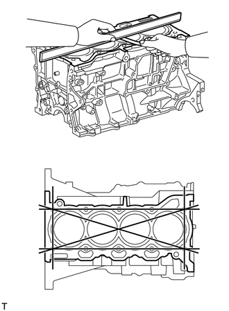
Using a straightedge and feeler gauge, check the surface which contacts the cylinder head gasket for warpage.
Maximum warpage 0.05 mm (0.00197 in.) If the warpage is greater than the maximum, replace the cylinder block sub-assembly.
-
-
INSPECT CYLINDER BORE
-
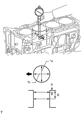
*a Thrust Direction *b Axial Direction 
Engine Front Using a cylinder gauge, measure the cylinder bore diameter at the positions (A) and (B) in both the thrust and axial directions.
Standard diameter 80.500 to 80.513 mm (3.1693 to 3.1698 in.) Maximum diameter 80.633 mm (3.1745 in.) Measurement Position Measurement Position Cylinder Bore Position A 10 mm (0.394 in.) from top edge B 50 mm (1.97 in.) from top edge If the average diameter of the 4 positions is more than the maximum, replace the cylinder block sub-assembly.
-
-
INSPECT PISTON
-
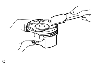
Using a gasket scraper, scrape off any carbon on the piston top.
-
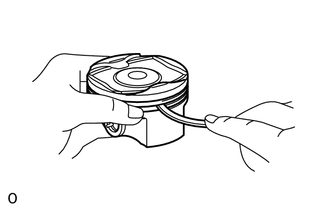
Using a groove cleaning tool or broken piston ring, clean the piston ring grooves.
-
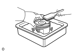
Using a brush and solvent, thoroughly clean the piston.
Note
Do not use a wire brush.
-
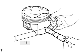
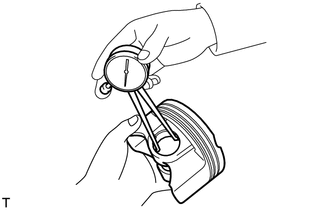
*1 12.6 mm Using a micrometer, measure the piston diameter at a position that is 12.6 mm (0.4961 in.) from the bottom of the piston (refer to the illustration).
Standard piston diameter 80.461 to 80.471 mm (3.1677 to 3.1681 in.) If the diameter is not as specified, replace the piston and piston pin.
-
-
INSPECT PISTON OIL CLEARANCE
-
Subtract the piston diameter measurement from the cylinder bore diameter measurement.
Standard oil clearance 0.029 to 0.052 mm (0.00114 to 0.00205 in.) Maximum oil clearance 0.09 mm (0.00354 in.) If the piston oil clearance is more than the maximum, replace all the pistons. If necessary, replace the cylinder block sub-assembly.
-
-
INSPECT RING GROOVE CLEARANCE
-
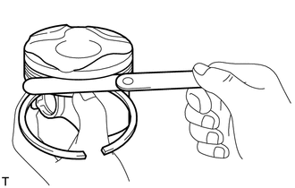
Using a feeler gauge, measure the clearance between a new piston ring and the wall of the ring groove.
Standard Ring Groove Clearance Item Specified Condition No. 1 Compression Ring 0.02 to 0.07 mm (0.000787 to 0.00276 in.) No. 2 Compression Ring 0.02 to 0.06 mm (0.000787 to 0.00236 in.) Oil Ring
(2-piece Type)
0.02 to 0.065 mm (0.000787 to 0.00256 in.) Oil Ring
(3-piece Type)
0.07 to 0.13 mm (0.00276 to 0.00512 in.) If the groove clearance is not as specified, replace the piston and piston pin.
-
-
INSPECT PISTON RING END GAP
-
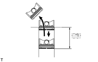
*1 50 mm Using a piston, push the piston ring a little beyond the bottom of the ring travel, 50 mm (1.97 in.) from the top of the cylinder block sub-assembly.
-
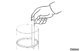
Using a feeler gauge, measure the end gap.
Standard End Gap Item Specified Condition No. 1 Ring 0.20 to 0.30 mm (0.00787 to 0.0118 in.) No. 2 Ring 0.30 to 0.50 mm (0.0118 to 0.0197 in.) Oil Ring
(2-piece Type)
0.10 to 0.40 mm (0.00394 to 0.0157 in.) Oil Ring
(3-piece Type)
0.10 to 0.35 mm (0.00394 to 0.0138 in.) Maximum End Gap Item Specified Condition No. 1 Ring 0.50 mm (0.0197 in.) No. 2 Ring 0.70 mm (0.0276 in.) Oil Ring 0.70 mm (0.0276 in.) If the end gap is more than the maximum, replace the piston ring. If the end gap is more than the maximum even with a new piston ring, replace the cylinder block sub-assembly.
-
-
INSPECT PISTON PIN OIL CLEARANCE
Tech Tips
There is only 1 type of supply part for piston with pin sub-assembly.
-
Using a caliper gauge, measure the piston pin bore diameter.
Standard piston pin bore diameter 20.006 to 20.015 mm (0.7876 to 0.7880 in.) Mark Specified Condition A 20.006 to 20.009 mm (0.78764 to 0.78775 in.) B 20.010 to 20.012 mm (0.78779 to 0.78787 in.) C 20.013 to 20.015 mm (0.78791 to 0.78799 in.) If the diameter is not as specified, replace the piston and piston pin.
-
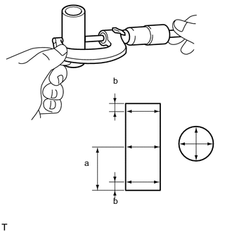
Using a micrometer, measure the piston pin diameter.
Standard piston pin diameter 20.004 to 20.013 mm (0.7876 to 0.7879 in.) Mark Specified Condition A 20.004 to 20.007 mm (0.78756 to 0.78768 in.) B 20.008 to 20.010 mm (0.78771 to 0.78779 in.) C 20.011 to 20.013 mm (0.78783 to 0.78791 in.) If the diameter is not as specified, replace the piston pin.
Measurement Position Measurement Position Piston Pin Position a 25 mm (0.984 in.) from side edge b 5 mm (0.197 in.) from side edge -
Using a caliper gauge, measure the connecting rod small end bore diameter.
Standard connecting rod small end bore diameter 20.012 to 20.021 mm (0.7879 to 0.7882 in.) Mark Specified Condition A 20.012 to 20.015 mm (0.78787 to 0.78799 in.) B 20.016 to 20.018 mm (0.78803 to 0.78811 in.) C 20.019 to 20.021 mm (0.78815 to 0.78823 in.) If the diameter is not as specified, replace the connecting rod.
-
Subtract the piston pin diameter measurement from the piston pin bore diameter measurement.
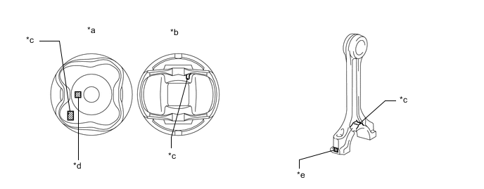
*a Upper Side *b Lower Side *c Front Mark *d Piston Pin Bore Diameter Mark *e Connecting Rod Small Bore Diameter Mark - - Standard oil clearance -0.001 to 0.005 mm (-0.0000394 to 0.000197 in.) Maximum oil clearance 0.010 mm (0.000394 in.) If the oil clearance is more than the maximum, replace the connecting rod. If necessary, replace the piston and piston pin as a set.
-
Subtract the piston pin diameter measurement from the connecting rod small end bore diameter measurement.
Standard oil clearance 0.005 to 0.011 mm (0.000197 to 0.000433 in.) Maximum oil clearance 0.014 mm (0.000551 in.) If the oil clearance is more than the maximum, replace the connecting rod small end bush. If necessary, replace the piston and piston pin as a set.
-
-
INSPECT CONNECTING ROD BOLT
-
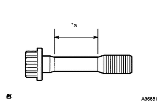
*a Measurement Area Using a vernier caliper, measure the diameter of the connecting rod bolt in the area shown in the illustration.
Standard diameter 6.6 to 6.7 mm (0.2598 to 0.2638 in.) Minimum diameter 6.4 mm (0.2520 in.) If the diameter is less than the minimum, replace the connecting rod bolt with a new one.
-
-
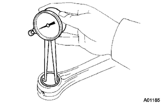
INSPECT CONNECTING ROD SUB-ASSEMBLY
-
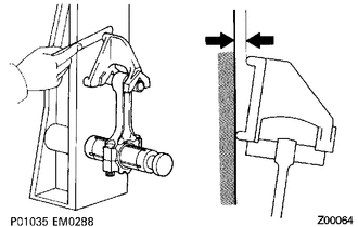
Using a connecting rod sub-assembly aligner and feeler gauge, check the connecting rod sub-assembly alignment.
-
Check for misalignment.
Maximum misalignment 0.05 mm (0.00197 in.) per 100 mm (3.94 in.) If the misalignment is more than the maximum, replace the connecting rod sub-assembly.
-
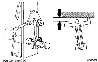
Check for twist.
Maximum twist 0.15 mm (0.00591 in.) per 100 mm (3.94 in.) If the twist is more than the maximum, replace the connecting rod sub-assembly.
-
-
-
INSPECT CRANKSHAFT
-
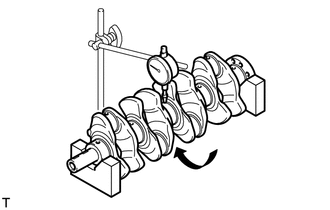
Using a dial indicator and V-blocks, measure the runout as shown in the illustration.
Maximum runout 0.03 mm (0.00118 in.) If the runout is greater than the maximum, replace the crankshaft.
-
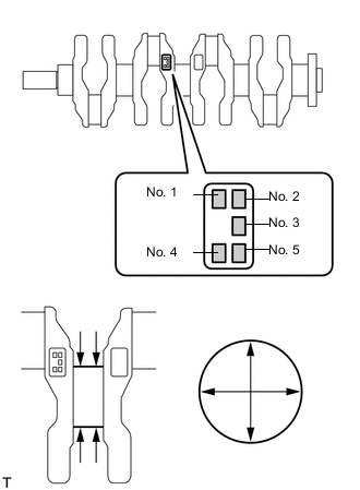
Using a micrometer, measure the diameter of each main journal.
Standard diameter 47.988 to 48.000 mm (1.8893 to 1.8898 in.) If the diameter is not as specified, check the crankshaft oil clearance.
-
Check each main journal for taper and out-of-round as shown in the illustration.
Maximum taper and out-of-round 0.004 mm (0.000157 in.) If the taper or out-of-round is greater than the maximum, replace the crankshaft.
Standard Diameter (Reference) Mark Specified Condition 0 47.999 to 48.000 mm (1.88972 to 1.88976 in.) 1 47.997 to 47.998 mm (1.88964 to 1.88968 in.) 2 47.995 to 47.996 mm (1.88956 to 1.88960 in.) 3 47.993 to 47.994 mm (1.88948 to 1.88952 in.) 4 47.991 to 47.992 mm (1.88941 to 1.88945 in.) 5 47.988 to 47.990 mm (1.88929 to 1.88937 in.) -
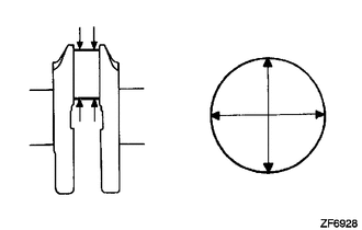
Using a micrometer, measure the diameter of each crank pin.
Standard diameter 43.992 to 44.000 mm (1.7320 to 1.7323 in.) If the diameter is not as specified, check the connecting rod oil clearance.
-
Inspect each crank pin for taper and out-of-round.
Maximum taper and out-of-round 0.004 mm (0.000157 in.) If the taper or out-of-round is greater than the maximum, replace the crankshaft.
-
-
INSPECT CRANKSHAFT THRUST CLEARANCE
-
Install the crankshaft bearing cap.
-
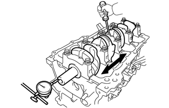
Using a dial indicator, measure the thrust clearance while prying the crankshaft back and forth with a screwdriver.
Standard thrust clearance 0.04 to 0.14 mm (0.00157 to 0.00551 in.) Maximum thrust clearance 0.18 mm (0.00709 in.) If the thrust clearance is greater than the maximum, replace the thrust washers as a set.
Tech Tips
The thrust washer thickness is 2.43 to 2.48 mm (0.0957 to 0.0976 in.).
-
-
INSPECT CRANKSHAFT OIL CLEARANCE
-
Check the crankshaft journal and crankshaft bearing for pitting and scratches.
-
Install the crankshaft bearing.
-
Clean each main journal and crankshaft bearing.
-
Place the crankshaft on the cylinder block sub-assembly.
-
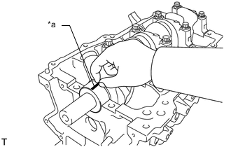
*a Plastigage Lay a strip of Plastigage across each journal.
-
Confirm the front marks and number marks and place the crankshaft bearing caps on the cylinder block sub-assembly.
Tech Tips
A number mark is stamped on each main bearing cap to indicate the installation position.
-
Install the crankshaft bearing caps.
Note
Do not turn the crankshaft.
-
Remove the crankshaft bearing caps.
-
Measure the Plastigage at its widest point.
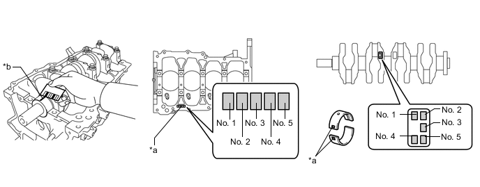
*a Number Mark *b Plastigage Standard oil clearance 0.016 to 0.039 mm (0.000630 to 0.00154 in.) Maximum oil clearance 0.050 mm (0.00197 in.) If the oil clearance is greater than the maximum, replace the crankshaft bearing. If necessary, replace the crankshaft.
Note
Remove the Plastigage completely after the measurement.
Tech Tips
If replacing a crankshaft bearing, select a new one with the same number. If the number of the crankshaft bearing cannot be determined, calculate the correct crankshaft bearing number by adding together the numbers imprinted on the cylinder block sub-assembly and crankshaft. Then select a new crankshaft bearing with the calculated number according to the chart below. There are 4 sizes of standard crankshaft bearings, marked "1", "2", "3" or "4" accordingly.
-
Example:
Cylinder block sub-assembly "3" + Crankshaft "5" = Total number 8 (Use crankshaft bearing "3")
Bearing Chart Cylinder Block sub-assembly + Crankshaft Bearing to be Used 0 to 2 "1" 3 to 5 "2" 6 to 8 "3" 9 to 11 "4"
Standard Cylinder Block Journal Bore Diameter Mark Specified Condition 0 52.000 to 52.002 mm (2.04724 to 2.04732 in.) 1 52.003 to 52.004 mm (2.04736 to 2.04740 in.) 2 52.005 to 52.006 mm (2.04744 to 2.04748 in.) 3 52.007 to 52.009 mm (2.04752 to 2.04759 in.) 4 52.010 to 52.011 mm (2.04763 to 2.04767 in.) 5 52.012 to 52.013 mm (2.04771 to 2.04775 in.) 6 52.014 to 52.016 mm (2.04779 to 2.04787 in.) Standard Crankshaft Journal Diameter Mark Specified Condition 0 47.999 to 48.000 mm (1.88972 to 1.88976 in.) 1 47.997 to 47.998 mm (1.88964 to 1.88968 in.) 2 47.995 to 47.996 mm (1.88956 to 1.88961 in.) 3 47.993 to 47.994 mm (1.88948 to 1.88952 in.) 4 47.991 to 47.992 mm (1.88941 to 1.88945 in.) 5 47.988 to 47.990 mm (1.88929 to 1.88937 in.) Standard Bearing Center Wall Thickness Mark Specified Condition 1 1.994 to 1.997 mm (0.07850 to 0.07862 in.) 2 1.998 to 2.000 mm (0.07866 to 0.07874 in.) 3 2.001 to 2.003 mm (0.07878 to 0.07886 in.) 4 2.004 to 2.006 mm (0.07890 to 0.07898 in.) -
-
-
INSPECT CRANKSHAFT BEARING CAP SET BOLT
-
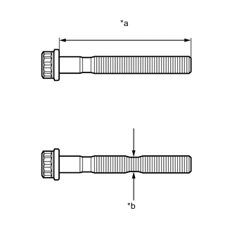
*a Measurement Length *b Measurement Point Using a vernier caliper, measure the length of the crankshaft bearing cap set bolt from the seat to the end.
Standard length 84.3 to 85.7 mm (3.3189 to 3.3740 in.) Maximum length 86.7 mm (3.4134 in.) If the length is more than the maximum, replace the crankshaft bearing cap set bolt with a new one.
-
Using a vernier caliper, measure the diameter of the threaded portion of the crankshaft bearing cap set bolt at its thinnest point shown in the illustration.
Standard diameter 9.77 to 9.96 mm (0.3846 to 0.3921 in.) Minimum diameter 9.1 mm (0.3583 in.) If the diameter is less than the minimum, replace the crankshaft bearing cap set bolt with a new one.
-
-
INSPECT NO. 1 OIL NOZZLE SUB-ASSEMBLY
-
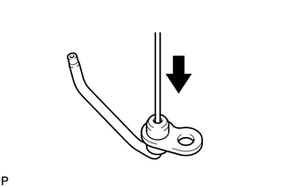
Push the check valve with a pin to check if it is stuck.
If stuck, replace the No. 1 oil nozzle sub-assembly.
-
Push the check valve with a pin to check if it moves smoothly.
If it does not move smoothly, clean or replace the No. 1 oil nozzle sub-assembly.
-
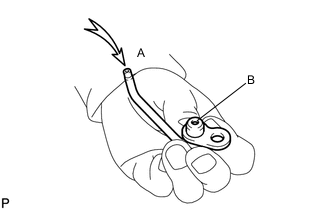
Apply air into A. Check that air does not leak through B.
If air leaks, clean or replace the No. 1 oil nozzle sub-assembly.
-
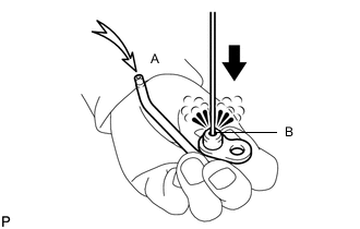
Push the check valve while applying air into A. Check that air passes through B.
If air does not pass through B, clean or replace the No. 1 oil nozzle sub-assembly.
-