REAR CRANKSHAFT OIL SEAL REMOVAL

CAUTION / NOTICE / HINT
Note
for Manual Transaxle:
When the manual transaxle is removed, be sure to use a new clutch release with bearing cylinder and new installation bolts. Removal of the manual transaxle allows the compressed clutch release with bearing cylinder to return to its original position, and dust could damage the seal of the clutch release with bearing cylinder, possibly causing clutch fluid leaks.
PROCEDURE
-
REMOVE CONTINUOUSLY VARIABLE TRANSAXLE ASSEMBLY (for CVT)
-
REMOVE CLUTCH DISC ASSEMBLY (for Manual Transaxle)
-
REMOVE DRIVE PLATE AND RING GEAR SUB-ASSEMBLY (for CVT)
-
Using height adjustment attachments and plate lift attachments, place the engine assembly on a flat, level surface.
Note
-
Using height adjustment attachments and plate lift attachments, place the engine assembly horizontally.
-
To prevent the oil pan sub-assembly from deforming, do not place any attachments under the oil pan sub-assembly of the engine assembly.
-
Using an engine sling device and engine lift, secure the engine assembly before servicing.
-
-
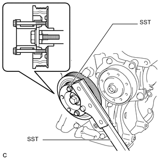
Using SST, hold the crankshaft.
for 86 mm (3.39 in.) Bolt Pitch Type:
- SST
- 09213-58014 ( 91551-80840 )
- 09330-00021
for 64 mm (2.52 in.) Bolt Pitch Type:
- SST
- 09213-54015
Tech Tips
For the 64 mm (2.52 in.) bolt pitch type, the part number of the installation bolt for SST (crankshaft pulley holding tool) is 91551-00850 (quantity: 2).
-
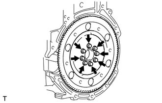
Remove the 8 bolts, the rear drive plate spacer, the drive plate and ring gear sub-assembly and the front drive plate spacer.
-
-
REMOVE FLYWHEEL SUB-ASSEMBLY (for Manual Transaxle)
-
Using height adjustment attachments and plate lift attachments, place the engine assembly on a flat, level surface.
Note
-
Using height adjustment attachments and plate lift attachments, place the engine assembly horizontally.
-
To prevent the oil pan sub-assembly from deforming, do not place any attachments under the oil pan sub-assembly of the engine assembly.
-
Using an engine sling device and engine lift, secure the engine assembly before servicing.
-
-
Using SST, hold the crankshaft.
for 86 mm (3.39 in.) Bolt Pitch Type:
- SST
- 09213-58014 ( 91551-80840 )
- 09330-00021
for 64 mm (2.52 in.) Bolt Pitch Type:
- SST
- 09213-54015
Tech Tips
For the 64 mm (2.52 in.) bolt pitch type, the part number of the installation bolt for SST (crankshaft pulley holding tool) is 91551-00850 (quantity: 2).
-
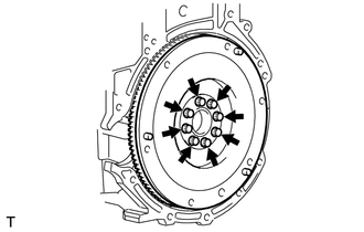
Remove the 8 bolts and the flywheel sub-assembly.
-
-
REMOVE REAR ENGINE OIL SEAL
-
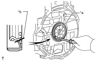
*a Protective Tape *b Cut Position Using a knife, cut off the rear engine oil seal lip.
-
Using a screwdriver with its tip wrapped with protective tape, pry out the rear engine oil seal.
Note
After removing, check the crankshaft and cylinder block sub-assembly for damage. If damaged, smooth the surface with 400-grit sandpaper.
-