ENGINE ASSEMBLY REMOVAL
CAUTION / NOTICE / HINT
CAUTION:
The engine assembly with transaxle is very heavy. Be sure to follow the procedure described in the repair manual, or the engine lifter may suddenly drop.
Note
for Manual Transaxle:
When the manual transaxle assembly transaxle is removed, be sure to use a new clutch release with bearing cylinder assembly and new installation bolts. Removal of the manual transaxle assembly allows the compressed clutch release with bearing cylinder assembly to return to its original position, and dust from the moving section could damage the seal of the clutch release with bearing cylinder assembly, possibly causing clutch fluid leaks.
PROCEDURE
-
PRECAUTION
Note
After turning the ignition switch off, waiting time may be required before disconnecting the cable from the negative (-) battery terminal. Therefore, make sure to read the disconnecting the cable from the negative (-) battery terminal notices before proceeding with work.
-
RECOVER REFRIGERANT FROM REFRIGERATION SYSTEM (w/ Air Conditioning System)
-
DISCHARGE FUEL SYSTEM PRESSURE
-
PLACE FRONT WHEELS FACING STRAIGHT AHEAD
-
DISCONNECT CABLE FROM NEGATIVE BATTERY TERMINAL
Note
When disconnecting the cable, some systems need to be initialized after the cable is reconnected.
-
REMOVE FRONT WHEEL
-
REMOVE FRONT LOWER BUMPER ABSORBER
-
Remove the 8 bolt, 4 screws and front lower bumper absorber.
-
-
REMOVE NO. 1 ENGINE UNDER COVER (for Full Cover Type)
-
Remove the 2 bolts, 13 clips and No. 1 engine under cover.
-
-
REMOVE NO. 1 ENGINE UNDER COVER (for Half Cover Type)
-
Remove the 2 bolts, 7 clips and No. 1 engine under cover.
-
-
REMOVE CENTER NO. 4 ENGINE UNDER COVER (w/ Cover)
-
for Full Cover Type:
-
Remove the 2 clips and center No. 4 engine under cover.
-
-
for Half Cover Type:
-
Remove the 5 clips and center No. 4 engine under cover.
-
-
-
REMOVE FRONT NO. 3 ENGINE UNDER COVER (for Full Cover Type)
-
Remove the 4 clips and front No. 3 engine under cover.
-
-
REMOVE REAR ENGINE UNDER COVER LH
-
Remove the 5 clips and rear engine under cover LH.
-
-
REMOVE REAR ENGINE UNDER COVER RH
-
Remove the 5 clips and rear engine under cover RH.
-
-
DRAIN ENGINE COOLANT
-
DRAIN CONTINUOUSLY VARIABLE TRANSAXLE FLUID (for CVT)
-
DRAIN MANUAL TRANSAXLE OIL (for Manual Transaxle)
-
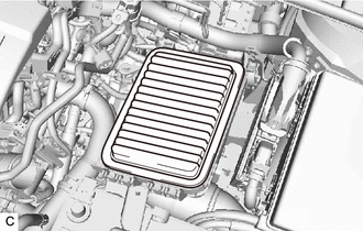
REMOVE NO. 2 CYLINDER HEAD COVER
-

Disengage the 2 rear side clips first. 
Disengage the 2 front side clips next. Lift the rear of the No. 2 cylinder head cover and to disengage the 2 rear clips. Lift the front of the No. 2 cylinder head cover to disengage the 2 front clips and remove the No. 2 cylinder head cover.
Note
Attempting to disengage both front and rear clips at the same time may cause the No. 2 cylinder head cover to break.
-
-
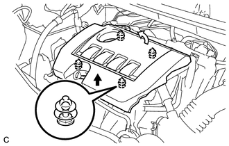
REMOVE AIR CLEANER CAP SUB-ASSEMBLY
-
REMOVE AIR CLEANER CASE SUB-ASSEMBLY
-
Remove the air cleaner filter element sub-assembly from the air cleaner case sub-assembly.
-
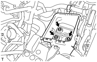
Remove the 3 bolts from the air cleaner case sub-assembly.
-
-
REMOVE BATTERY
-
Loosen the nut, and separate the positive (+) battery terminal.
-
Remove the bolt and nut.
-
Remove the battery clamp sub-assembly and battery clamp bolt.
-
Remove the battery and battery tray from the battery carrier assembly.
-
-
REMOVE BATTERY CARRIER ASSEMBLY
-
Disconnect the 2 wire harness clamps from the battery carrier assembly.
-
Remove the 2 bolts.
-
Disconnect the radiator pipe from the battery carrier assembly.
-
Remove the 4 bolts and battery carrier assembly.
-
-
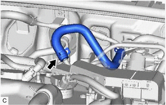
DISCONNECT NO. 1 RADIATOR HOSE (for CVT)
-
Disconnect the breather plug hose from the clamp.
-
Slide the clip and disconnect the No. 1 radiator hose from the cylinder head sub-assembly.
-
-
DISCONNECT NO. 1 RADIATOR HOSE (for Manual Transaxle)
-
Slide the clip and disconnect the No. 1 radiator hose from the cylinder head sub-assembly.
-
-
DISCONNECT NO. 2 RADIATOR HOSE
-
Slide the clip and disconnect the No. 2 radiator hose from the water inlet.
-
-
DISCONNECT TRANSMISSION CONTROL CABLE ASSEMBLY (for CVT)
-
Remove the nut and disconnect the transmission control cable assembly from the control shaft lever.
-
Remove the clip and separate the transmission control cable assembly from the No. 1 transmission control cable bracket.
-
Remove the bolt and disconnect the transmission control cable assembly from the rear engine mounting insulator.
-
-
DISCONNECT TRANSMISSION CONTROL CABLE ASSEMBLY (for Manual Transaxle)
-
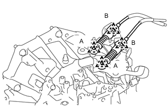
Remove the 2 clips (A) and disconnect the 2 transmission control cable assemblies from the manual transaxle.
-
Remove the 2 clips (B) and disconnect the 2 transmission control cable assemblies from the control cable bracket.
-
Remove the bolt and disconnect the transmission control cable assembly from the rear engine mounting bracket.
-
-
DISCONNECT NO. 1 FUEL VAPOR FEED HOSE
-
Slide the clip and disconnect the No. 1 fuel vapor feed hose from the duty vacuum switching valve.
-
-
DISCONNECT UNION TO VACUUM TUBE HOSE (for LHD)
-
Slide the clip and disconnect the union to vacuum tube hose from the air tube.
-
-
DISCONNECT UNION TO VACUUM TUBE HOSE (for RHD)
-
Slide the clip and disconnect the union to vacuum tube hose from the air tube.
-
-
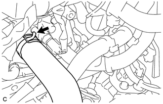
DISCONNECT HEATER WATER OUTLET HOSE A
-
DISCONNECT HEATER WATER INLET HOSE A
-
DISCONNECT FUEL TUBE SUB-ASSEMBLY
-
Release the claw and remove the No. 1 fuel pipe clamp.
-
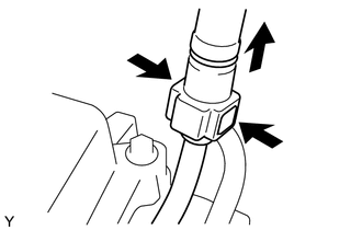
Pinch the retainer as shown in the illustration, then pull the fuel tube connector out of the fuel pipe.
Note
-
Remove any dirt and foreign matter from the fuel tube connector before performing this work.
-
Do not allow any scratches or foreign matter to get on the parts when disconnecting, as the fuel tube connector has the O-rings that seal the fuel pipe.
-
Perform this work by hand. Do not use any tools.
-
Do not forcibly bend, kink or twist the nylon fuel tube sub-assembly.
-
Protect the disconnected parts by covering it with a plastic bag after disconnecting the fuel tube sub-assembly.
-
If the fuel tube connector and fuel pipe are stuck, push and pull to release them.
-
-
-
REMOVE V-RIBBED BELT
-
REMOVE GENERATOR ASSEMBLY
-
DISCONNECT DISCHARGE HOSE SUB-ASSEMBLY (w/ Air Conditioning System)
-
DISCONNECT SUCTION HOSE SUB-ASSEMBLY (w/ Air Conditioning System)
-
REMOVE COMPRESSOR ASSEMBLY WITH PULLEY (w/ Air Conditioning System)
-
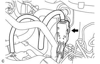
DISCONNECT WIRE HARNESS
-
Pull up the lever and disconnect the ECM connector.
-
Disconnect the wire harness clamp.
-
Remove the No. 1 relay block cover from the engine room relay block and junction block assembly.
-
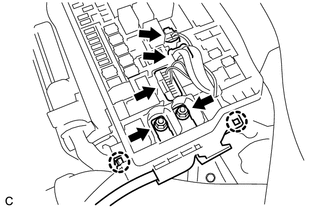
Remove the 2 nuts from the engine room relay block and junction block assembly.
-
Disconnect the 3 connectors and wire harness from the engine room relay block and junction block assembly and disengage the 2 claws.
-
for CVT:
-
Remove the bolt and disconnect the clamp and No. 3 engine wire from the CVT.
-
-
for Manual Transaxle:
-
Remove the bolt and disconnect the No. 3 engine wire from the manual transaxle.
-
-
Disconnect all the wire harnesses and connectors.
Tech Tips
Make sure that no wire harness is connected between the body and engine.
-
-
SECURE STEERING WHEEL
-
REMOVE COLUMN HOLE COVER SILENCER SHEET
-
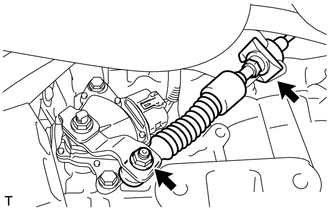
SEPARATE NO. 2 STEERING INTERMEDIATE SHAFT ASSEMBLY
-
SEPARATE NO. 1 STEERING COLUMN HOLE COVER SUB-ASSEMBLY
-
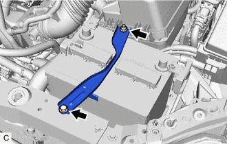
REMOVE FRONT CENTER FLOOR BRACE SUB-ASSEMBLY
-
REMOVE FRONT EXHAUST PIPE ASSEMBLY (TWC: Front and Rear Catalyst)
-
REMOVE FRONT DRIVE SHAFT ASSEMBLY
-
REMOVE FRONT ENGINE MOUNTING BRACKET LOWER REINFORCEMENT (w/ Reinforcement)
-
REMOVE FRONT SUSPENSION MEMBER REINFORCEMENT LH
-
REMOVE FRONT SUSPENSION MEMBER REINFORCEMENT RH
Tech Tips
Perform the same procedure as for the LH side.
-
REMOVE FLYWHEEL HOUSING UNDER COVER (for CVT)
-
Remove the flywheel housing under cover.
-
-
REMOVE DRIVE PLATE AND TORQUE CONVERTER ASSEMBLY SETTING BOLT (for CVT)
-
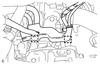
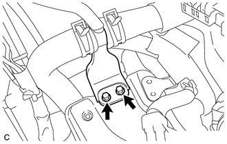
REMOVE FRONT SUSPENSION MEMBER REAR BRACE LH
-
REMOVE FRONT SUSPENSION MEMBER REAR BRACE RH
Tech Tips
Perform the same procedure as for the LH side.
-
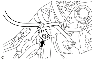
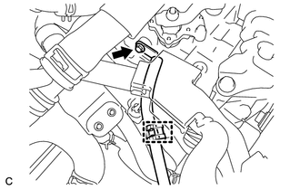
DISCONNECT CLUTCH HOSE (for Manual Transaxle)
-
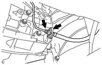
Using a 10 mm union nut wrench, disconnect the clutch hose from the flexible hose tube.
-
Remove the clip and disconnect the clutch hose.
-
-
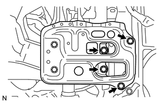
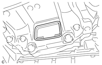
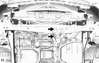
REMOVE FRONT SUSPENSION CROSSMEMBER SUB-ASSEMBLY
-
REMOVE ENGINE ASSEMBLY WITH TRANSAXLE
-
Set the engine lifter.
Note
-
Place a height adjustment attachments and plate lift attachments under the engine assembly with transaxle.
-
Do not position the height adjustments attachment or plate lift attachments under the front crossmember sub-assembly.
-
Do not perform any procedure while the engine assembly with transaxle is suspended because doing so may cause the engine assembly with transaxle to drop, resulting in injury. However, the engine assembly with transaxle needs to be suspended when it is installed to or removed from an engine stand.
-
-
Remove the 2 bolts to disconnect the front engine mounting insulator from the front crossmember sub-assembly.
-
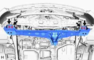
Remove the 4 bolts and front crossmember sub-assembly.
-
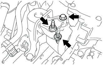
Remove the bolt and 2 nuts, and separate the engine mounting insulator sub-assembly RH.
-
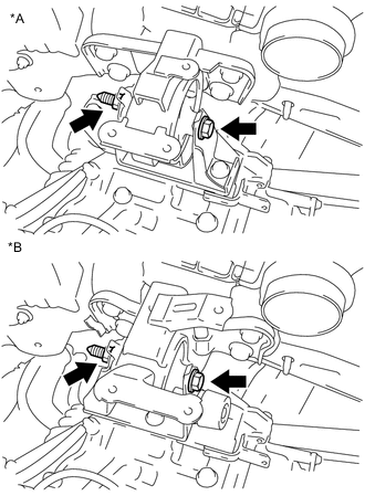
*A for CVT *B for Manual Transaxle Remove the through bolt and nut and separate the engine mounting insulator LH.
Tech Tips
When removing the through bolt, keep the nut from rotating.
-
Carefully remove the engine assembly with transaxle from the vehicle.
Note
Make sure that the engine assembly with transaxle is clear of all wiring and hoses.
-
-
REMOVE FRONT ENGINE MOUNTING INSULATOR
Tech Tips
Perform this procedure only when replacement of the front engine mounting insulator is necessary.
-
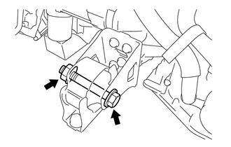
Remove the through bolt, nut and front engine mounting insulator from the front engine mounting bracket.
Tech Tips
Because the nut its own stopper, do not turn the nut. Loosen the bolt with the nut secured.
-
-
REMOVE REAR ENGINE MOUNTING INSULATOR (for CVT)
Tech Tips
Perform this procedure only when replacement of the rear engine mounting insulator is necessary.
-
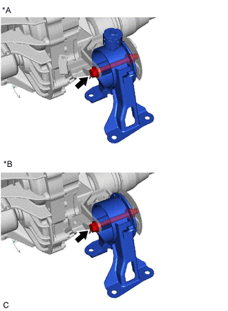
*A Type A *B Type B Remove the through bolt and rear engine mounting insulator from the rear engine mounting bracket.
-
-
REMOVE REAR ENGINE MOUNTING INSULATOR (for Manual Transaxle)
Tech Tips
Perform this procedure only when replacement of the rear engine mounting insulator is necessary.
-
Remove the through bolt and rear engine mounting insulator from the rear engine mounting bracket.
*A Type A *B Type B *C Type C - -
-
-
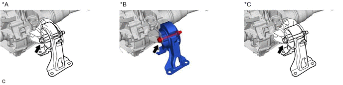
REMOVE ENGINE MOUNTING INSULATOR LH
Tech Tips
Perform this procedure only when replacement of the engine mounting insulator LH is necessary.
-
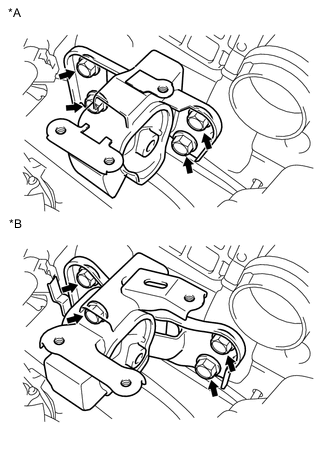
*A for CVT *B for Manual Transaxle Remove the 4 bolts and engine mounting insulator LH.
-
-
REMOVE ENGINE MOUNTING INSULATOR SUB-ASSEMBLY RH
Tech Tips
Perform this procedure only when replacement of the engine mounting insulator sub-assembly RH is necessary.
-
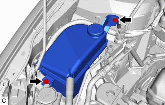
Remove the 2 bolts and disconnect the radiator reservoir tank.
-
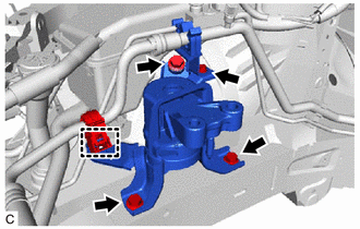
Remove the bolt and cooler pipe clamp bracket from the engine mounting insulator sub-assembly RH.
-
Disconnect the cooler pipe clamp from the engine mounting insulator sub-assembly RH.
-
Remove the 3 bolts and engine mounting insulator sub-assembly RH.
-
-
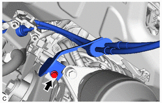
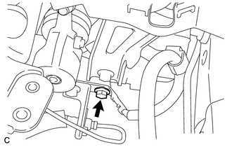
REMOVE WIRE HARNESS CLAMP BRACKET
-
Remove the bolt and wire harness clamp bracket.
-
-
INSTALL ENGINE HANGER
-
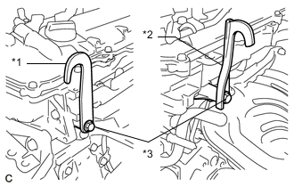
*1 No. 1 Engine Hanger (Part No.12281-37050) *2 No. 2 Engine Hanger (Part No.12282-37040) *3 Bolt (Part No.91552-81050) Install the No. 1 engine hanger and No. 2 engine hanger with the 2 bolts.
- Torque:
- 43 N*m { 439 kgf*cm, 32 ft.*lbf }
-
-
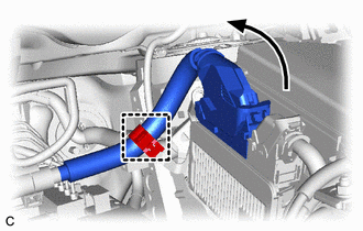
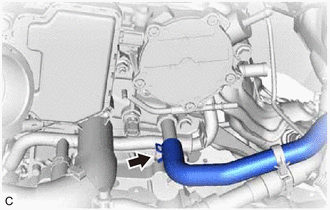
REMOVE HEATER WATER OUTLET HOSE A
-
Slide the clip and remove the heater water outlet hose A from the No. 1 water by-pass pipe.
-
-
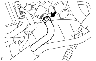
REMOVE HEATER WATER INLET HOSE A
-
Slide the clip and remove the heater water inlet hose A from the cylinder head sub-assembly.
-
-
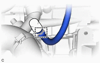
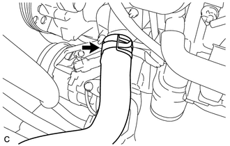
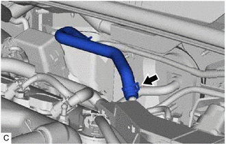
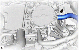
DISCONNECT NO. 5 WATER BY-PASS HOSE (for CVT)
-
Slide the clip and disconnect the No. 5 water by-pass hose from the No. 1 water by-pass pipe.
-
-
REMOVE FLYWHEEL HOUSING SIDE COVER
-
*a Protruding Portion *b Claw Remove the flywheel housing side cover from the stiffening crankcase assembly.
-
-
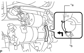
REMOVE STARTER ASSEMBLY
-
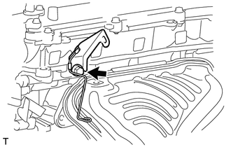
REMOVE ENGINE WIRE
-
Remove the engine wire from the engine assembly with transaxle.
-
-
REMOVE CONTINUOUSLY VARIABLE TRANSAXLE ASSEMBLY (for CVT)
-
REMOVE MANUAL TRANSAXLE ASSEMBLY (for Manual Transaxle)
-
REMOVE BLEEDER CLUTCH RELEASE TUBE (for Manual Transaxle)
-
REMOVE CLUTCH RELEASE BLEEDER SUB-ASSEMBLY (for Manual Transaxle)
-
REMOVE CLUTCH RELEASE WITH BEARING CYLINDER ASSEMBLY (for Manual Transaxle)
-
REMOVE CLUTCH RELEASE CYLINDER TO BLEEDER TUBE (for Manual Transaxle)
-
REMOVE CLUTCH COVER ASSEMBLY (for Manual Transaxle)
-
REMOVE CLUTCH DISC ASSEMBLY (for Manual Transaxle)
-
REMOVE DRIVE PLATE AND RING GEAR SUB-ASSEMBLY (for CVT)
-
REMOVE FLYWHEEL SUB-ASSEMBLY (for Manual Transaxle)
-
INSTALL ENGINE TO ENGINE STAND
-
Install the engine assembly to an engine stand.
Note
-
Adjust the angle of the sling device carefully to prevent the engine assembly or engine hanger from deforming or becoming damaged.
-
Servicing an engine assembly while it is hanging is dangerous. This can be done only when installing/removing the engine assembly to/from an engine stand.
-
-
-
REMOVE ENGINE HANGER
-
Remove the 2 bolts, No. 1 engine hanger and No. 2 engine hanger.
-