CYLINDER HEAD INSPECTION

PROCEDURE
-
INSPECT NO. 1 VALVE ROCKER ARM SUB-ASSEMBLY
-

Turn the roller by hand to check that it turns smoothly.
If the roller does not turn smoothly, replace the No. 1 valve rocker arm sub-assembly.
-
-
INSPECT VALVE LASH ADJUSTER ASSEMBLY
Note
-
Keep the valve lash adjuster assembly free from dirt and foreign matter.
-
Only use clean engine oil.
-
Place the valve lash adjuster assembly into a container full of new engine oil.
-
Insert the tip of SST into the plunger and use the tip to press down on the check ball inside the plunger.

*1 Plunger *2 Check Ball *3 Low Pressure Chamber *4 High Pressure Chamber *a Correct *b Incorrect *c Taper Part - - - SST
- 09276-75010
-
Squeeze SST and the valve lash adjuster assembly together to move the plunger up and down 5 to 6 times.
-
Check the movement of the plunger and bleed the air.
OK Plunger moves up and down. Note
When bleeding air from high-pressure chamber, make sure that the tip of SST is actually pressing the check ball as shown in the illustration. If the check ball is not pressed, air will not bleed.
-
After bleeding the air, remove SST. Then try to quickly and firmly press the plunger with your fingers.
OK Plunger is very difficult to move. If the result is not as specified, replace the valve lash adjuster assembly.
-
-
INSPECT CYLINDER HEAD FOR FLATNESS
-

*a Cylinder Head Lower Side *b Intake Manifold Side *c Exhaust Manifold Side Using a precision straightedge and feeler gauge, check the surfaces which contact the cylinder block sub-assembly and manifold for warpage.
Maximum Warpage Item Specified Condition Cylinder block side 0.05 mm (0.00197 in.) Intake manifold side 0.10 mm (0.00394 in.) Exhaust manifold side 0.10 mm (0.00394 in.) If the warpage is more than the maximum, replace the cylinder head.
-
-
INSPECT CYLINDER HEAD FOR CRACKS
-
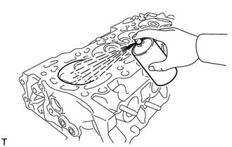
Using a dye penetrant, check the intake ports, exhaust ports and cylinder surface for cracks.
If cracked, replace the cylinder head.
-
-
INSPECT VALVE SEATS
-

*a Width Apply a light coat of Prussian blue to the valve face.
-
Lightly press the valve face against the valve seat.
Tech Tips
Do not rotate the valve while pressing the valve.
-
Check the valve face and valve seat.
-
Intake Side:
Check that the contact surfaces of the valve seat and valve face are in the middle area of their respective surfaces, with the width between 1.0 and 1.4 mm (0.0433 and 0.0551 in.).
If not, resurface the valve seat.
-
Exhaust Side:
Check that the contact surfaces of the valve seat and valve face are in the middle area of their respective surfaces, with the width between 1.0 and 1.4 mm (0.0433 and 0.0551 in.).
If not, resurface the valve seat.
-
Check that the contact surfaces of the valve seat and valve face are even around the entire valve seat.
If not, resurface the valve seat.
-
-
-
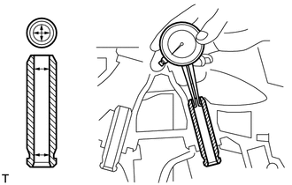
INSPECT CAMSHAFT THRUST CLEARANCE
-
Install the camshaft housing sub-assembly.
Tech Tips
Do not use seal packing when installing the camshaft housing sub-assembly, as the installation is temporary.
-

Using a dial indicator, measure the thrust clearance while moving the camshaft back and forth.
Standard thrust clearance 0.06 to 0.155 mm (0.00236 to 0.00610 in.) Maximum thrust clearance 0.17 mm (0.00669 in.) If the thrust clearance is more than the maximum, replace the camshaft housing sub-assembly.
-
-
INSPECT INNER COMPRESSION SPRING
Tech Tips
Type A and Type B can be distinguished by the shape of the compression spring.
Type Compression Spring Shape A Straight B Tapered 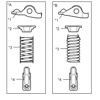
*A Type A *B Type B *1 No. 1 Valve Rocker Arm Sub-assembly *2 Valve Spring Retainer *3 Compression Spring *4 Valve Lash Adjuster Assembly
-
Type A:
-
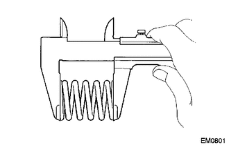
Using a vernier caliper, measure the free length of the inner compression spring.
Reference free length (New parts) 53.88 mm (2.12 in.) -
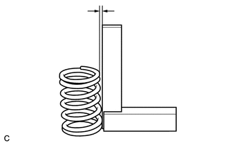
Using a steel square, measure the deviation of the inner compression spring.
Maximum deviation 1.0 mm (0.0394 in.) If the deviation is more than the maximum, replace the inner compression spring.
-
-
Type B:
-
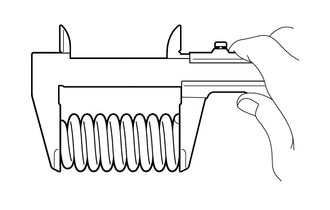
Using a vernier caliper, measure the free length of the inner compression spring.
Reference free length (New parts) 51.88 mm (2.042 in.) or 51.90 mm (2.043 in.) -
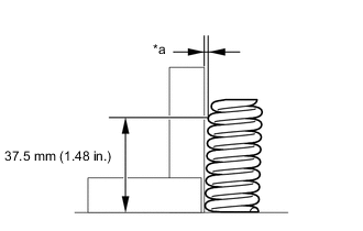
*a Deviation Using a steel square, measure the deviation of the inner compression spring.
Maximum deviation 1.3 mm (0.0512 in.) If the deviation is more than the maximum, replace the inner compression spring.
-
-
-
INSPECT INTAKE VALVE
-

*a Overall length Using a vernier caliper, measure the overall length of the intake valve.
Standard overall length 109.34 mm (4.30 in.) Minimum overall length 108.84 mm (4.29 in.) If the overall length is less than the minimum, replace the intake valve.
-
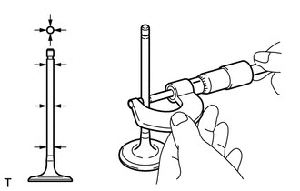
Using a micrometer, measure the diameter of the intake valve stem.
Standard valve stem diameter 5.470 to 5.485 mm (0.215 to 0.216 in.) If the intake valve stem diameter is not as specified, check the oil clearance.
-

*a Margin thickness Using a vernier caliper, measure the intake valve head margin thickness.
Standard margin thickness 1.0 mm (0.0394 in.) Minimum margin thickness 0.5 mm (0.0197 in.) If the margin thickness is less than the minimum, replace the intake valve.
-
-
INSPECT EXHAUST VALVE
-

*a Overall length Using a vernier caliper, measure the overall length of the exhaust valve.
Standard overall length 108.25 mm (4.26 in.) Minimum overall length 107.75 mm (4.24 in.) If the overall length is less than the minimum, replace the exhaust valve.
-
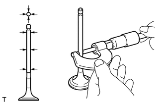
Using a micrometer, measure the diameter of the exhaust valve stem.
Standard valve stem diameter 5.465 to 5.480 mm (0.215 to 0.216 in.) If the exhaust valve stem diameter is not as specified, check the oil clearance.
-

*a Margin thickness Using a vernier caliper, measure the exhaust valve head margin thickness.
Standard margin thickness 1.0 mm (0.0394 in.) Minimum margin thickness 0.5 mm (0.0197 in.) If the margin thickness is less than the minimum, replace the exhaust valve.
-
-
INSPECT VALVE GUIDE BUSH OIL CLEARANCE
-
Using a caliper gauge, measure the inside diameter of the valve guide bush.
Standard bush inside diameter 5.510 to 5.530 mm (0.217 to 0.218 in.) -
Subtract the valve stem diameter measurement from the valve guide bush inside diameter measurement.
Standard Oil Clearance Item Specified Condition Intake 0.025 to 0.060 mm (0.000984 to 0.00236 in.) Exhaust 0.030 to 0.065 mm (0.00118 to 0.00256 in.) Maximum Oil Clearance Item Specified Condition Intake 0.080 mm (0.00315 in.) Exhaust 0.085 mm (0.00335 in.) If the clearance is more than the maximum, replace the valve and valve guide bush.
-