ENGINE ASSEMBLY INSTALLATION
CAUTION / NOTICE / HINT
CAUTION:
The engine assembly with transaxle is very heavy. Be sure to follow the procedure described in the repair manual, or the engine lifter may suddenly drop.
PROCEDURE
-
INSTALL ENGINE HANGERS
-
REMOVE ENGINE ASSEMBLY FROM ENGINE STAND
-
Remove the engine assembly from the engine stand.
-
-
INSTALL NO. 1 IDLER PULLEY SUB-ASSEMBLY (w/o Air Conditioning System)
-
Using an E8 "TORX" socket wrench, install the 2 stud bolts.
- Torque:
- 9.8 N*m { 100 kgf*cm, 87 in.*lbf }
-
Install the No. 1 idler pulley sub-assembly.
-
Install the bolt and 2 nuts.
- Torque:
- 25 N*m { 255 kgf*cm, 18 ft.*lbf }
-
-
INSTALL NO. 1 IDLER PULLEY (w/o Air Conditioning System)
Tech Tips
Perform this procedure only when replacement of the No. 1 idler pulley is necessary.
-
Install the No. 1 idler pulley and 2 idler pulley cover plate to the idler pulley bracket with the bolt.
- Torque:
- 60 N*m { 612 kgf*cm, 44 ft.*lbf }
-
-
INSTALL COMPRESSOR ASSEMBLY WITH PULLEY (w/ Air Conditioning System)
-
INSTALL GENERATOR ASSEMBLY
-
INSTALL V-RIBBED BELT TENSIONER ASSEMBLY
-
Install the V-ribbed belt tensioner assembly to the timing chain cover assembly with the 2 bolts.
- Torque:
- 21 N*m { 214 kgf*cm, 15 ft.*lbf }
-
-
INSTALL V-RIBBED BELT
-
INSTALL DRIVE PLATE AND RING GEAR SUB-ASSEMBLY (for CVT)
-
INSTALL FLYWHEEL SUB-ASSEMBLY (for Manual Transaxle)
-
INSTALL CONTINUOUSLY VARIABLE TRANSAXLE ASSEMBLY (for CVT)
-
INSTALL CLUTCH DISC ASSEMBLY (for Manual Transaxle)
-
INSTALL ENGINE WIRE
-
Connect all connectors and clamps, and install the engine wire to the engine assembly with transaxle.
-
-
INSTALL STARTER ASSEMBLY
w/o Stop And Start System: Click here
for Transaxle CVT with Stop and Start System: Click here
for Transaxle M/T with Stop and Start System: Click here
-
INSTALL FLYWHEEL HOUSING SIDE COVER
w/o Stop And Start System: Click here
for Transaxle CVT with Stop and Start System: Click here
for Transaxle M/T with Stop and Start System: Click here
-
INSTALL WATER HOSE (for CVT)
-
Install the water hose to engine assembly with transaxle and slide the 5 clips to secure them.
-
Engage the 4 clamps to the engine assembly with transaxle.
-
-
INSTALL WATER HOSE (for Manual Transaxle)
-
Install the water hose to engine assembly with transaxle and slide the 3 clips to secure them.
-
Engage the 3 clamps to the engine assembly with transaxle.
-
-
INSTALL ENGINE MOUNTING INSULATOR SUB-ASSEMBLY RH
Tech Tips
Perform this procedure only when replacement of the engine mounting insulator sub-assembly RH is necessary.
-
Install the engine mounting insulator sub-assembly RH to the vehicle body with the 3 bolts.
- Torque:
- 95 N*m { 969 kgf*cm, 70 ft.*lbf }
-
Connect the cooler pipe clamp to the engine mounting insulator sub-assembly RH.
-
Install the cooler pipe clamp bracket to the engine mounting insulator sub-assembly RH with the bolt.
- Torque:
- 9.8 N*m { 100 kgf*cm, 87 in.*lbf }
-
Install the intercooler reserve tank assembly to the vehicle body with the 2 bolts.
- Torque:
- 5.0 N*m { 51 kgf*cm, 44 in.*lbf }
-
-
INSTALL ENGINE MOUNTING INSULATOR LH
Tech Tips
Perform this procedure only when replacement of the engine mounting insulator LH is necessary.
-
Install the engine mounting insulator LH to the vehicle body with the 4 bolts.
- Torque:
- 95 N*m { 969 kgf*cm, 70 ft.*lbf }
-
-
TEMPORARILY INSTALL REAR ENGINE MOUNTING INSULATOR
Tech Tips
Perform this procedure only when replacement of the rear engine mounting insulator is necessary.
-
Temporarily install the rear engine mounting insulator to the rear engine mounting bracket with the bolt.
-
-
TEMPORARILY INSTALL FRONT ENGINE MOUNTING INSULATOR
Tech Tips
Perform this procedure only when replacement of the front engine mounting insulator is necessary.
-
Temporarily install the front engine mounting insulator to the front engine mounting bracket with the bolt and nut.
-
-
INSTALL ENGINE ASSEMBLY WITH TRANSAXLE
-
Set the engine assembly with transaxle on an engine lifter.
Note
-
Using height adjustment attachments and plate lift attachments, keep the engine assembly with transaxle horizontal.
-
Do not perform any procedures while the engine assembly is suspended because doing so may cause the engine assembly to drop, resulting in injury. However, the engine assembly needs to be suspended when it is installed to or removed from an engine stand.
-
To prevent the oil pan sub-assembly from deforming, do not place any attachments under the oil pan sub-assembly of the engine assembly with transaxle.
-
-
Operate the engine lifter and install the engine assembly with transaxle to the vehicle.
CAUTION:
Do not raise the engine assembly with transaxle more than necessary. If the engine is raised excessively, the vehicle may also be lifted up.
Note
-
Make sure that the engine assembly with transaxle is clear of all wiring and hoses.
-
While raising the engine assembly with transaxle into the vehicle, do not allow it to contact the vehicle.
-
-
Install the engine mounting insulator LH to the engine mounting bracket LH with the bolt and nut.
- Torque:
- 56 N*m { 571 kgf*cm, 41 ft.*lbf }
Note
While holding the bolt in place, tighten the nut.
-
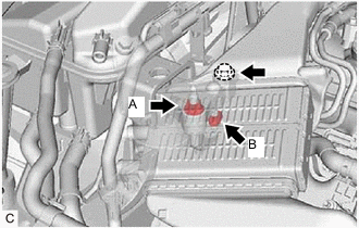
Install the engine mounting insulator sub-assembly RH to the engine mounting bracket RH with the bolt and 2 nuts.
- Torque:
- Bolt
- 95 N*m { 969 kgf*cm, 70 ft.*lbf }
- Nut (A)
- 95 N*m { 969 kgf*cm, 70 ft.*lbf }
- Nut (B)
- 52 N*m { 530 kgf*cm, 38 ft.*lbf }
-
Install the front crossmember sub-assembly to the vehicle body with the 4 bolts.
- Torque:
- 99 N*m { 1010 kgf*cm, 73 ft.*lbf }
-
Install the front engine mounting insulator to the front crossmember sub-assembly with the 2 bolts.
- Torque:
- 95 N*m { 969 kgf*cm, 70 ft.*lbf }
-
-
REMOVE ENGINE HANGERS
-
INSTALL WIRE HARNESS CLAMP BRACKET
-
Install the wire harness clamp bracket to the cylinder head sub-assembly with the bolt.
- Torque:
- 39 N*m { 398 kgf*cm, 29 ft.*lbf }
-
Engage the clamp with the wire harness clamp bracket.
-
Connect the wire harness to the wire harness clamp bracket.
-
-
INSTALL FRONT SUSPENSION CROSSMEMBER SUB-ASSEMBLY
-
INSTALL FRONT SUSPENSION MEMBER REAR BRACE LH
-
INSTALL FRONT SUSPENSION MEMBER REAR BRACE RH
Tech Tips
Use the same procedure as for the LH side.
-
INSTALL DRIVE PLATE AND TORQUE CONVERTER ASSEMBLY SETTING BOLT (for CVT)
-
CONNECT CLUTCH HOSE (for Manual Transaxle)
-
Install a new clip and connect the clutch hose to the clutch flexible hose bracket.
-
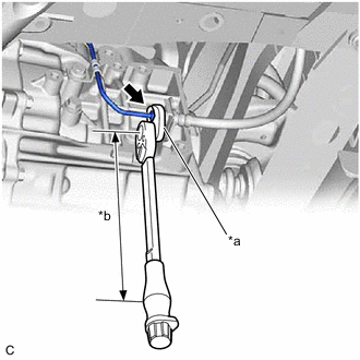
*a 10 mm Union Nut Wrench *b Torque Wrench Fulcrum Length Using a 10 mm union nut wrench, connect the bleeder clutch release tube to the clutch hose.
- Torque:
- Specified tightening torque
- 15.2 N*m { 155 kgf*cm, 11 ft.*lbf }
Tech Tips
-
Calculate the torque wrench reading when changing the fulcrum length of the torque wrench.
-
When using a 10 mm union nut wrench (fulcrum length of 22 mm (0.866 in.)) + torque wrench (fulcrum length of 162 mm (6.38 in.)): 13.4 N*m (137 kgf*cm, 10 ft.*lbf)
-
-
INSTALL FLYWHEEL HOUSING UNDER COVER
-
Install the flywheel housing under cover to the stiffening crankcase assembly.
-
-
INSTALL FRONT SUSPENSION MEMBER REINFORCEMENT LH
-
INSTALL FRONT SUSPENSION MEMBER REINFORCEMENT RH
-
INSTALL FRONT ENGINE MOUNTING BRACKET LOWER REINFORCEMENT (w/ Reinforcement)
-
INSTALL REAR ENGINE MOUNTING INSULATOR
Tech Tips
Perform this procedure only when replacement of the rear engine mounting insulator is necessary.
-
Tighten the bolt of the rear engine mounting insulator.
- Torque:
- 95 N*m { 969 kgf*cm, 70 ft.*lbf }
-
-
INSTALL FRONT ENGINE MOUNTING INSULATOR
Tech Tips
Perform this procedure only when replacement of the front engine mounting insulator is necessary.
-
Tighten the bolt and nut of the front engine mounting insulator.
- Torque:
- 85 N*m { 867 kgf*cm, 63 ft.*lbf }
Note
While holding the nut in place, tighten the bolt.
-
-
INSTALL FRONT DRIVE SHAFT ASSEMBLY
-
INSTALL FRONT EXHAUST PIPE ASSEMBLY (TWC: Rear Catalyst)
-
INSTALL FRONT CENTER FLOOR BRACE SUB-ASSEMBLY
-
CONNECT NO. 1 STEERING COLUMN HOLE COVER SUB-ASSEMBLY
-
CONNECT NO. 2 STEERING INTERMEDIATE SHAFT ASSEMBLY
-
INSTALL COLUMN HOLE COVER SILENCER SHEET
-
CONNECT WIRE HARNESS
-
Connect the 2 wire harness clamps to the battery carrier assembly.
-
Connect the cable to the positive (+) battery terminal and tighten the nut.
- Torque:
- 5.4 N*m { 55 kgf*cm, 48 in.*lbf }
-
for CVT:
-
Connect the No. 3 engine wire to the continuously variable transaxle assembly with the bolt.
- Torque:
- 12.5 N*m { 127 kgf*cm, 9 ft.*lbf }
-
Engage the clamp to the wire harness clamp bracket.
-
-
for Manual Transaxle:
-
Connect the No. 3 engine wire to the manual transaxle assembly with the bolt.
- Torque:
- 12.5 N*m { 127 kgf*cm, 9 ft.*lbf }
-
-
Engage the 2 claws and connect the wire harness to the engine room relay block assembly.
-
Install the 2 nuts to the engine room relay block assembly.
- Torque:
- 8.5 N*m { 87 kgf*cm, 75 in.*lbf }
-
Connect the 3 connectors to the engine room relay block assembly.
-
Install the No. 1 relay block cover to the engine room relay block assembly.
-
Connect the ECM connector and lower the lever.
Note
-
When connecting the ECM connector, make sure that the connecting parts of the ECM connector are free of dirt, water or other foreign matter.
-
Be sure to securely connect the ECM connector.
-
-
Engage the wire harness clamp.
-
-
CONNECT SUCTION HOSE SUB-ASSEMBLY (w/ Air Conditioning System)
-
CONNECT DISCHARGE HOSE SUB-ASSEMBLY (w/ Air Conditioning System)
-
CONNECT FUEL TUBE SUB-ASSEMBLY
-
CONNECT HEATER WATER INLET HOSE A
-
CONNECT HEATER WATER OUTLET HOSE A
-
CONNECT FUEL VAPOR FEED HOSE
-
Connect the fuel vapor feed hose to the fuel vapor feed pipe and slide the clip to secure it.
-
-
CONNECT UNION TO CONNECTOR TUBE HOSE
-
CONNECT TRANSMISSION CONTROL CABLE ASSEMBLY (for CVT)
-
Connect the transmission control cable assembly to the rear engine mounting insulator with the bolt.
- Torque:
- 5.0 N*m { 51 kgf*cm, 44 in.*lbf }
-
Connect the transmission control cable assembly to the No. 1 transmission control cable bracket with a new clip.
-
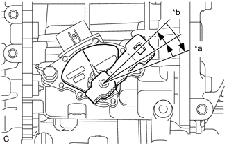
*a P Position *b N Position Turn the control shaft lever clockwise until it stops, then turn it counterclockwise 2 notches.
-
Connect the transmission control cable assembly to the control shaft lever with the nut.
- Torque:
- 12 N*m { 122 kgf*cm, 9 ft.*lbf }
-
-
CONNECT TRANSMISSION CONTROL CABLE ASSEMBLY (for Manual Transaxle)
-
Connect the transmission control cable assembly to the rear engine mounting insulator with the bolt.
- Torque:
- 5.0 N*m { 51 kgf*cm, 44 in.*lbf }
-
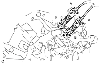
Connect the transmission control cable assembly to the control cable bracket assembly with 2 new clips (A).
-
Connect the transmission control cable assembly to the manual transaxle assembly with the 2 clips (B).
-
-
CONNECT NO. 4 TURBO WATER HOSE
-
CONNECT NO. 1 TURBO WATER HOSE
-
CONNECT NO. 2 RADIATOR HOSE
-
CONNECT NO. 1 RADIATOR HOSE
-
INSTALL AIR CLEANER CASE SUB-ASSEMBLY
-
Install the air cleaner case sub-assembly to the engine mounting insulator LH with the 3 bolts.
- Torque:
- 7.0 N*m { 71 kgf*cm, 62 in.*lbf }
-
Install the wire harness clamp to the air cleaner case sub-assembly.
-
Install the air cleaner filter element sub-assembly to the air cleaner case sub-assembly.
-
-
INSTALL AIR CLEANER CAP WITH AIR CLEANER HOSE
-
CONNECT CABLE TO NEGATIVE BATTERY TERMINAL
-
Connect the cable to the negative (-) battery terminal with the nut.
- Torque:
- 5.4 N*m { 55 kgf*cm, 48 in.*lbf }
Note
When disconnecting the cable, some systems need to be initialized after the cable is reconnected.
-
-
BLEED CLUTCH LINE (for Manual Transaxle)
-
ADD ENGINE OIL
-
ADD ENGINE COOLANT
-
ADD COOLANT (for Intercooler)
-
ADD MANUAL TRANSAXLE OIL (for Manual Transaxle)
-
ADD CONTINUOUSLY VARIABLE TRANSAXLE FLUID
-
CHARGE AIR CONDITIONING SYSTEM WITH REFRIGERANT (w/ Air Conditioning System)
-
WARM UP ENGINE (w/ Air Conditioning System)
-
INSPECT TRANSAXLE OIL (for Manual Transaxle)
-
ADJUST SHIFT LEVER POSITION (for Manual Transaxle)
-
INSPECT SHIFT LEVER POSITION (for CVT)
for TMMT Made: Click here
for TMUK Made: Click here
-
ADJUST SHIFT LEVER POSITION (for CVT)
for TMMT Made: Click here
for TMUK Made: Click here
-
INSPECT FOR ENGINE OIL LEAK
-
INSPECT FOR COOLANT LEAK
-
INSPECT FOR COOLANT LEAK (for Intercooler)
-
INSPECT FOR CONTINUOUSLY VARIABLE TRANSAXLE FLUID LEAK
-
INSPECT FOR REFRIGERANT LEAK (w/ Air Conditioning System)
-
INSPECT FOR FUEL LEAK
-
INSPECT FOR EXHAUST GAS LEAK
-
CHECK ENGINE OIL LEVEL
-
INSPECT ENGINE COOLANT LEVEL IN RESERVOIR
-
INSTALL REAR ENGINE UNDER COVER RH
-
Install the rear engine under cover RH with the 5 clips.
-
-
INSTALL REAR ENGINE UNDER COVER LH
-
Install the rear engine under cover LH with the 5 clips.
-
-
INSTALL CENTER NO. 4 ENGINE UNDER COVER (w/ Cover)
-
for Full Cover Type:
-
Install the center No. 4 engine under cover with the 2 clips.
-
-
for Half Cover Type:
-
Install the center No. 4 engine under cover with the 5 clips.
-
-
-
INSTALL NO. 1 ENGINE UNDER COVER
-
for Full Cover Type:
-
Install the No. 1 engine under cover with the 2 bolts and 11 clips.
-
-
for Half Cover Type:
-
Install the No. 1 engine under cover with the 2 bolts and 7 clips.
-
-
-
INSTALL FRONT LOWER BUMPER ABSORBER
-
Install the front lower bumper absorber with the 8 bolts and 4 screws.
-
-
INSTALL NO. 1 ENGINE COVER SUB-ASSEMBLY
-
Engage the 2 rear retainers, then the front retainer to install the No. 1 engine cover sub-assembly.
Note
-
Be sure to engage the retainers securely.
-
Do not apply excessive force or tap the No. 1 engine cover sub-assembly to engage the retainers. This may cause the No. 1 engine cover sub-assembly to break.
-
-
-
INSTALL FRONT WHEELS
- Torque:
- 103 N*m { 1050 kgf*cm, 76 ft.*lbf }
-
ALIGN FRONT WHEELS FACING STRAIGHT AHEAD
-
INSPECT AND ADJUST FRONT WHEEL ALIGNMENT
-
PERFORM INITIALIZATION
-
INSPECT IGNITION TIMING
-
INSPECT ENGINE IDLE SPEED
-
INSPECT CO/HC
-
CHECK SPEED SENSOR SIGNAL