CAMSHAFT INSTALLATION
CAUTION / NOTICE / HINT
Tech Tips
Perform "Inspection After Repair" after replacing the camshaft, No. 2 camshaft, camshaft timing gear assembly or camshaft timing exhaust gear assembly.
PROCEDURE
-
SET NO. 1 VALVE ROCKER ARM SUB-ASSEMBLY
-
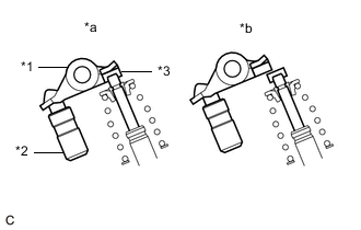
*1 No. 1 Valve Rocker Arm Sub-assembly *2 Valve Lash Adjuster Assembly *3 Valve Stem Cap *a Correct *b Incorrect Make sure that the No. 1 valve rocker arm sub-assemblies are installed as shown in the illustration.
-
-
INSTALL CAMSHAFT HOUSING SUB-ASSEMBLY
-
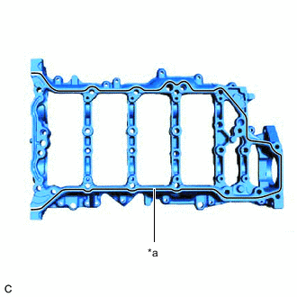
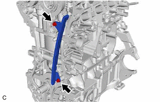
*a Seal Packing Apply seal packing in a continuous line as shown in the illustration.
Seal Packing Toyota Genuine Seal Packing Black, Three Bond 1207B or equivalent Seal Packing Diameter 3.5 to 4.0 mm (0.138 to 0.157 in.) Note
-
Remove any oil from the contact surface.
-
Install the camshaft housing sub-assembly within 3 minutes and tighten the bolts within 15 minutes of applying seal packing.
-
Do not start the engine for at least 2 hours after installation.
-
-
Set the camshaft housing sub-assembly to the cylinder head sub-assembly.
-
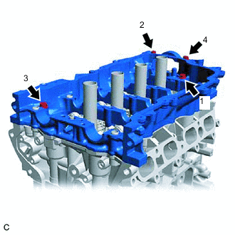
Tighten the 4 bolts in the order shown in the illustration.
- Torque:
- 28 N*m { 286 kgf*cm, 21 ft.*lbf }
-
-
INSTALL OIL CONTROL VALVE FILTER
-
INSTALL NO. 2 CAMSHAFT
-
Clean the No. 2 camshaft journals.
-
Apply a light coat of engine oil to the No. 2 camshaft journals and camshaft housing sub-assembly.
-
Install the No. 2 camshaft to the camshaft housing sub-assembly.
-
-
INSTALL CAMSHAFT
-
Clean the camshaft journals.
-
Apply a light coat of engine oil to the camshaft journals and camshaft housing sub-assembly.
-
Install the camshaft to the camshaft housing sub-assembly.
-
-
INSTALL CAMSHAFT BEARING CAP
-
INSTALL WATER VALVE
-
INSTALL CAMSHAFT TIMING EXHAUST GEAR ASSEMBLY
-
INSTALL CAMSHAFT TIMING GEAR ASSEMBLY
-
SET NO. 1 CYLINDER TO TDC/COMPRESSION
-
INSTALL CHAIN SUB-ASSEMBLY
Tech Tips
-
Be sure to install the chain sub-assembly with the mark plates facing away from the engine assembly.
-
Pass the chain sub-assembly through the timing chain guide.
-
Temporarily install the crankshaft pulley set bolt.
-
Install the timing chain guide with the 2 bolts to the cylinder head sub-assembly and cylinder block sub-assembly.
- Torque:
- 10 N*m { 102 kgf*cm, 7 ft.*lbf }
-
Align the mark plates (gold) with the timing marks as shown in the illustration and install the chain sub-assembly.
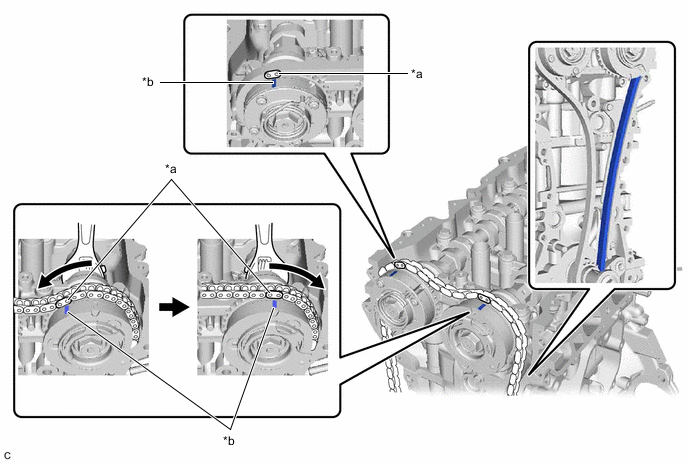
*a Mark Plate (Gold) *b Timing Mark Tech Tips
Do not pass the chain sub-assembly around the sprocket of the camshaft timing gear assembly. Only place it on the sprocket.
-
Hold the hexagonal portion of the camshaft with a wrench and turn the camshaft timing gear assembly clockwise.
Tech Tips
To tension the chain sub-assembly, slowly turn the camshaft timing gear assembly clockwise to prevent the chain sub-assembly from being misaligned.
-
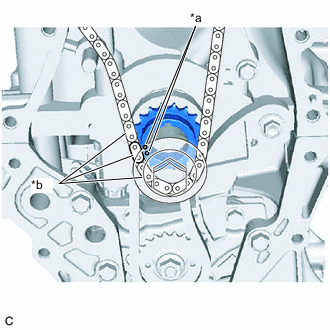
*a Timing Mark *b Mark Plate (Gold) Align the mark plate (gold) and timing mark and install the chain sub-assembly to the crankshaft timing sprocket.
Note
The mark for the crankshaft spans 3 outer links. Use the center mark plate for the alignment.
-
Remove the crankshaft pulley set bolt from the crankshaft.
-
-
INSTALL CHAIN TENSIONER SLIPPER
-
INSTALL NO. 1 CHAIN TENSIONER ASSEMBLY
-
CHECK NO. 1 CYLINDER TDC/COMPRESSION
-
INSTALL WATER INLET PIPE
-
INSTALL TIMING CHAIN COVER OIL SEAL
-
INSTALL TIMING CHAIN COVER ASSEMBLY
-
INSTALL CRANKSHAFT PULLEY
-
INSTALL SPARK PLUG TUBE GASKET
-
INSTALL CYLINDER HEAD COVER GASKET
-
ADD ENGINE OIL
-
INSTALL CYLINDER HEAD COVER SUB-ASSEMBLY
-
INSTALL CAMSHAFT TIMING OIL CONTROL SOLENOID ASSEMBLY (for Exhaust Side)
-
INSTALL CAMSHAFT TIMING OIL CONTROL SOLENOID ASSEMBLY (for Intake Side)
-
INSTALL VACUUM PUMP ASSEMBLY
-
INSTALL ENGINE OIL LEVEL DIPSTICK GUIDE
-
INSTALL WATER BY-PASS PIPE SUB-ASSEMBLY
-
INSTALL FUEL VAPOR FEED PIPE
-
INSTALL NO. 1 IGNITION COIL
-
INSTALL FUEL PUMP ASSEMBLY
-
INSTALL FUEL INJECTOR ASSEMBLY
-
INSTALL TURBOCHARGER SUB-ASSEMBLY
-
INSTALL ENGINE HANGERS
-
REMOVE ENGINE ASSEMBLY FROM ENGINE STAND