ENGINE UNIT DISASSEMBLY

PROCEDURE
-
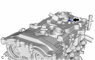
REMOVE OIL FILLER CAP SUB-ASSEMBLY
-
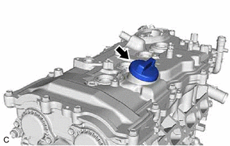
Remove the oil filler cap sub-assembly from the cylinder head cover sub-assembly.
-
-
REMOVE OIL FILLER CAP GASKET
-
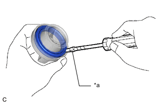
*a Protective Tape Using a screwdriver with its tip wrapped with protective tape, remove the oil filler cap gasket from the oil filler cap sub-assembly.
-
-
REMOVE SPARK PLUG
-
REMOVE CAMSHAFT POSITION SENSOR (for Intake Side)
-
REMOVE CAMSHAFT POSITION SENSOR (for Exhaust Side)
-
REMOVE CAMSHAFT TIMING OIL CONTROL SOLENOID ASSEMBLY (for Intake Side)
-
REMOVE CAMSHAFT TIMING OIL CONTROL SOLENOID ASSEMBLY (for Exhaust Side)
-
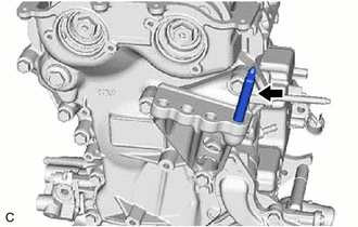
REMOVE ENGINE OIL LEVEL DIPSTICK GUIDE
-
Remove the engine oil level dipstick from the engine oil level dipstick guide.
-
Remove the bolt and engine oil level dipstick guide from the camshaft housing sub-assembly.
-
Remove the engine oil level dipstick guide O-ring from the engine oil level dipstick guide.
-
-
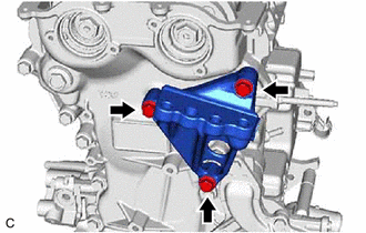
REMOVE GENERATOR BRACKET
-
Remove the bolt and generator bracket from the cylinder block sub-assembly.
-
-
REMOVE KNOCK CONTROL SENSOR
-
REMOVE CRANKSHAFT POSITION SENSOR
-
REMOVE ENGINE OIL TEMPERATURE SENSOR
-
REMOVE OIL PRESSURE SENDER GAUGE ASSEMBLY
-
REMOVE OIL PRESSURE SWITCHING VALVE ASSEMBLY
-
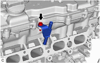
REMOVE OIL PUMP RELIEF VALVE HOUSING ASSEMBLY
-
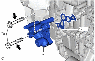
*1 Oil Pump Relief Valve Hosing Assembly *2 Oil Regulator Body Gasket *a Bolt Remove the 2 bolts, oil pump relief valve hosing assembly and oil regulator body gasket from the cylinder block sub-assembly.
-
-
REMOVE CYLINDER HEAD COVER SUB-ASSEMBLY
-
Remove the cover joint from the cylinder head cover sub-assembly.
-
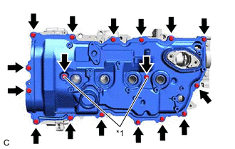
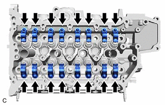
*1 Cylinder Head Cover Seal Washer Remove the 17 bolts, 2 cylinder head cover seal washers, and cylinder head cover sub-assembly from the camshaft housing sub-assembly.
-
Remove the 3 gaskets from the camshaft bearing cap.
Note
As gaskets may stick to the cylinder head cover sub-assembly, be careful not to drop any of the gaskets into the engine when removing the cylinder head cover sub-assembly.
-
-
REMOVE CYLINDER HEAD COVER GASKET
-
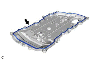
Remove the cylinder head cover gasket from the cylinder head cover sub-assembly.
-
-
REMOVE SPARK PLUG TUBE GASKET
-
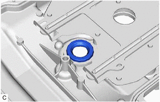
Remove the 4 spark plug tube gaskets from the cylinder head cover sub-assembly.
-
-
REMOVE OIL FILTER SUB-ASSEMBLY
-
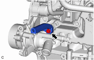
REMOVE OIL FILTER UNION
-
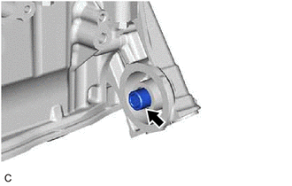
Using a 12 mm hexagon socket wrench, remove the oil filter union from the timing chain cover assembly.
-
-
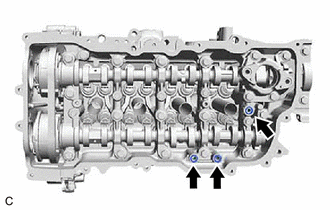
SET NO. 1 CYLINDER TO TDC/COMPRESSION
-
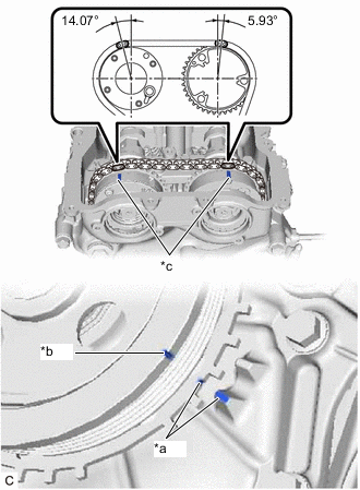
*a Timing Mark (TDC) *b Cutout *c Timing Mark Turn the crankshaft pulley until its cutout is aligned with the timing mark (TDC) of the timing chain cover assembly.
-
Check that the timing marks on both the camshaft timing exhaust gear assembly and camshaft timing gear assembly are facing upward as shown in the illustration.
Tech Tips
If the timing marks are not facing upwards, turn the crankshaft 1 complete revolution (360°) and align the timing marks as above.
-
-
REMOVE CRANKSHAFT PULLEY
-
REMOVE WATER INLET WITH THERMOSTAT SUB-ASSEMBLY
-
REMOVE NO. 2 WATER INLET HOUSING GASKET
-
REMOVE STUD BOLT
Note
If a stud bolt is deformed or its threads are damaged, replace it.
-
Remove the stud bolt from the engine mounting bracket RH.
-
-
REMOVE ENGINE MOUNTING BRACKET RH
-
Remove the 3 bolts and engine mounting bracket RH from the timing chain cover assembly.
-
-
REMOVE ENGINE WATER PUMP ASSEMBLY
-
REMOVE TIMING CHAIN COVER ASSEMBLY
-
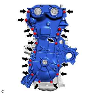
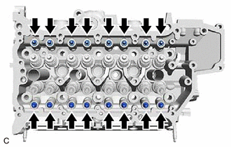
Remove the 17 bolts from the timing chain cover assembly.
-
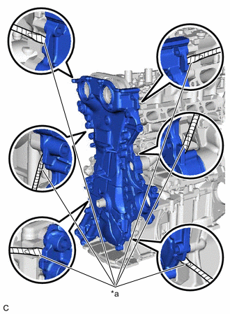
*a Protective Tape Remove the timing chain cover assembly by prying between the timing chain cover assembly and cylinder head sub-assembly, camshaft housing sub-assembly, cylinder block sub-assembly and stiffening crankcase assembly with a screwdriver with its tip wrapped with protective tape.
Note
Be careful not to damage the contact surfaces of the cylinder head sub-assembly, camshaft housing sub-assembly, cylinder block sub-assembly, stiffening crankcase assembly and timing chain cover assembly.
-
-
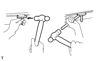
REMOVE TIMING CHAIN COVER OIL SEAL
-
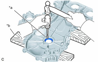
*a Protective Tape *b Wooden Block Place the timing chain cover assembly on wooden blocks.
-
Using a hammer and a screwdriver with its tip wrapped with protective tape, tap out the timing chain cover oil seal.
Note
Be careful not to damage the timing chain cover assembly.
-
-
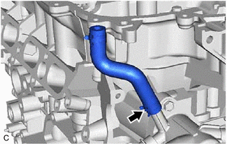
REMOVE WATER INLET PIPE
-
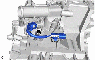
Remove the water inlet pipe from the water inlet.
-
Remove the 2 water inlet O-rings from the water inlet pipe.
-
-
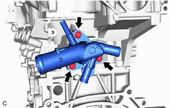
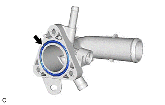
REMOVE WATER INLET
-
REMOVE THERMOSTAT (for Cylinder Block)
-
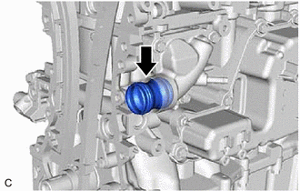
REMOVE NO. 1 CHAIN TENSIONER ASSEMBLY
-
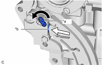
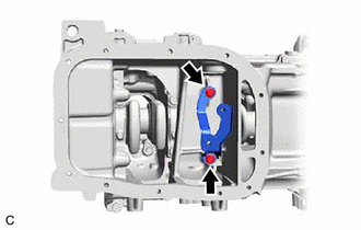
*a Stopper Plate *b Plunger 
Push Turn the stopper plate of the No. 1 chain tensioner assembly counterclockwise to release the lock and push in the plunger.
-
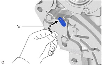
*a Pin Turn the stopper plate clockwise to set the lock, and insert a pin into the stopper plate hole.
-
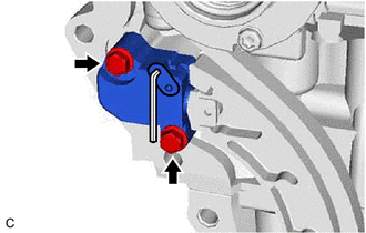
Remove the 2 bolts and No. 1 chain tensioner assembly from the cylinder head sub-assembly.
-
-
REMOVE CHAIN TENSIONER SLIPPER
-
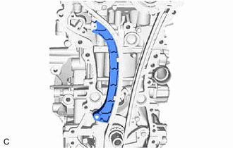
Remove the chain tensioner slipper from the cylinder block sub-assembly.
-
-
REMOVE TIMING CHAIN GUIDE
-
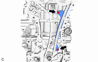
Remove the 2 bolts and timing chain guide from the cylinder block sub-assembly and cylinder head sub-assembly.
-
-
REMOVE CHAIN SUB-ASSEMBLY
-
REMOVE CRANKSHAFT TIMING SPROCKET
-
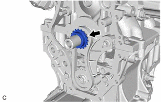
Remove the crankshaft timing sprocket from the crankshaft.
-
-
REMOVE NO. 2 CHAIN SUB-ASSEMBLY
-
Temporarily install the crankshaft pulley with the crankshaft pulley set bolt.
-
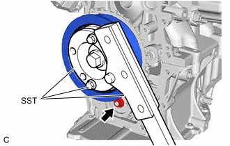
Using SST, hold the crankshaft pulley. Then remove the oil pump drive shaft gear nut.
- SST
- 09213-70011 ( 09213-70020 )
- 09330-00021
-
Remove SST, the crankshaft pulley set bolt and crankshaft pulley.
-
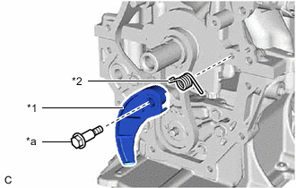
*1 Chain Tensioner Plate *2 Chain Damper Spring *a Bolt Remove the bolt, chain tensioner plate and chain damper spring.
-
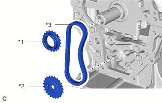
*1 Oil Pump Drive Gear *2 Oil Pump Drive Shaft Gear *3 No. 2 Chain Sub-assembly Remove the oil pump drive gear, oil pump drive shaft gear and No. 2 chain sub-assembly.
-
-
REMOVE CAMSHAFT TIMING GEAR ASSEMBLY
-
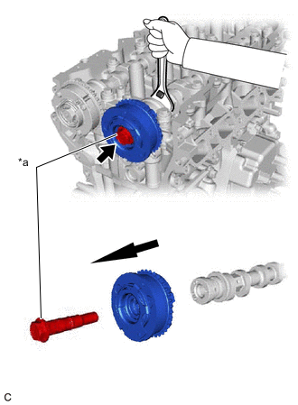
*a Camshaft Timing Gear Bolt (for Intake Side) Remove the camshaft timing gear bolt (for intake side) while holding the hexagonal portion of the camshaft, and then remove the camshaft timing gear assembly.
Note
-
If the camshaft timing gear bolt (for intake side) has been struck or dropped, replace it.
-
Keep the camshaft timing gear assembly horizontal while removing it from the camshaft.
-
Do not disassemble the camshaft timing gear assembly.
-
-
-
REMOVE CAMSHAFT TIMING EXHAUST GEAR ASSEMBLY
-
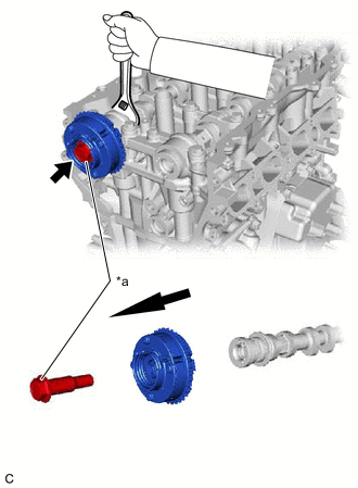
*a Camshaft Timing Gear Bolt (for Exhaust Side) Remove the camshaft timing gear bolt (for exhaust side) while holding the hexagonal portion of the No. 2 camshaft, and then remove the camshaft timing exhaust gear assembly.
Note
-
If the camshaft timing gear bolt (for exhaust side) has been struck or dropped, replace it.
-
Keep the camshaft timing exhaust gear assembly horizontal while removing it from the No. 2 camshaft.
-
Do not disassemble the camshaft timing exhaust gear assembly.
-
-
-
REMOVE CAMSHAFT BEARING CAP
-
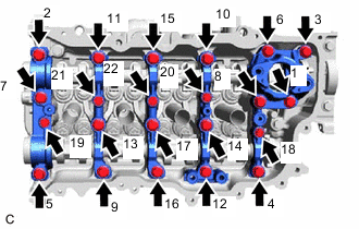
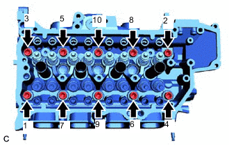
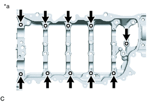
Uniformly loosen and remove the 22 bolts in the order shown in the illustration.
Note
Make sure that the camshaft and No. 2 camshaft remain level while uniformly loosening the bolts.
-
Remove the 5 camshaft bearing caps from the camshaft housing sub-assembly.
Tech Tips
Arrange the removed parts in such a way that they can be reinstalled to their original locations.
-
-
REMOVE CAMSHAFT
-
REMOVE NO. 2 CAMSHAFT
-
REMOVE OIL CONTROL VALVE FILTER
-
Remove the oil control valve filter from the camshaft housing sub-assembly.
-
-
REMOVE WATER VALVE
-
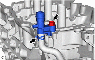
Remove the bolt to disconnect the water valve from the camshaft housing sub-assembly.
-
Slide the clip and remove the water valve from the No. 7 water by-pass hose.
-
-
REMOVE NO. 7 WATER BY-PASS HOSE
-
Slide the clip and remove the No. 7 water by-pass hose from the water outlet.
-
-
REMOVE NO. 5 ENGINE WIRE
-
Disconnect the engine coolant temperature sensor connector.
-
Disengage the wire harness clamp and remove the No. 5 engine wire from the water outlet.
-
-
REMOVE ENGINE COOLANT TEMPERATURE SENSOR
-
REMOVE WATER OUTLET
-
Remove the 3 bolts and water outlet from the cylinder head sub-assembly.
-
-
REMOVE WATER OUTLET GASKET
-
Remove the water outlet gasket from the water outlet.
-
-
REMOVE CAMSHAFT HOUSING SUB-ASSEMBLY
-
REMOVE NO. 1 VALVE ROCKER ARM SUB-ASSEMBLY
-
Remove the 16 No. 1 valve rocker arm sub-assemblies from the cylinder head sub-assembly.
Tech Tips
Arrange the removed parts in such a way that they can be reinstalled to their original locations.
-
-
REMOVE VALVE LASH ADJUSTER ASSEMBLY
-
Remove the 16 valve lash adjuster assemblies from the cylinder head sub-assembly.
Tech Tips
Arrange the removed parts in such a way that they can be reinstalled to their original locations.
-
-
REMOVE VALVE STEM CAP
-
Remove the 16 valve stem caps from the cylinder head sub-assembly.
Tech Tips
Arrange the removed parts in such a way that they can be reinstalled to their original locations.
-
-
REMOVE CYLINDER HEAD SUB-ASSEMBLY
-
Using a 10 mm bi-hexagon socket wrench, uniformly loosen and remove the 10 cylinder head set bolts and 10 cylinder head set plate washers in several steps in the order shown in the illustration.
Note
-
Do not drop the cylinder head set plate washers into the cylinder head sub-assembly.
-
Removing the cylinder head set bolts in the incorrect order may cause warpage or cracking of the cylinder head sub-assembly.
Tech Tips
Arrange the removed parts in such a way that they can be reinstalled to their original locations.
-
-
Remove the cylinder head sub-assembly.
-
-
REMOVE CYLINDER HEAD GASKET
-
REMOVE OIL PAN DRAIN PLUG
-
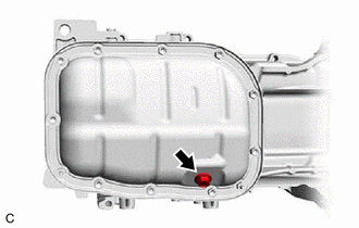
Remove the oil pan drain plug and oil pan drain plug gasket from the No. 2 oil pan sub-assembly.
-
-
REMOVE NO. 2 OIL PAN SUB-ASSEMBLY
-
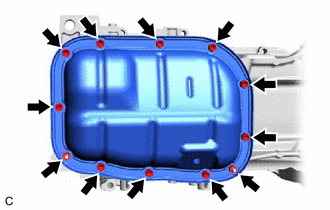
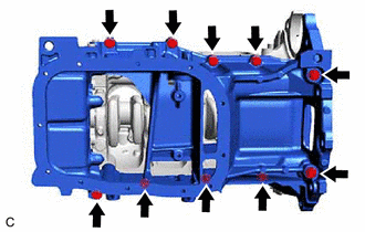
Remove the 10 bolts and 2 nuts from the No. 2 oil pan sub-assembly.
-
Insert the blade of an oil pan seal cutter between the stiffening crankcase assembly and No. 2 oil pan sub-assembly. Cut through the applied sealer and remove the No. 2 oil pan sub-assembly.
Note
-
Be careful not to damage the surface of the No. 2 oil pan sub-assembly which contacts the stiffening crankcase assembly.
-
Be careful not to damage the flange of the stiffening crankcase assembly.
-
-
-
REMOVE STUD BOLT
Note
If a stud bolt is deformed or its threads are damaged, replace it.
-
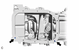
Using an E6 "TORX" socket wrench, remove the 2 stud bolts from the stiffening crankcase assembly.
-
-
REMOVE OIL PUMP ASSEMBLY
-
REMOVE ENGINE OIL LEVEL SENSOR
-
REMOVE SENSOR BRACKET
-
Remove the 2 bolts and sensor bracket from the stiffening crankcase assembly.
-
-
REMOVE STIFFENING CRANKCASE ASSEMBLY
-
Uniformly loosen and remove the 10 bolts from the stiffening crankcase assembly.
-
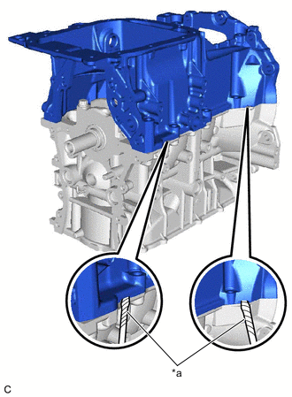
*a Protective Tape Remove the stiffening crankcase assembly by prying between the stiffening crankcase assembly and cylinder block sub-assembly with a screwdriver with its tip wrapped with protective tape.
Note
Be careful not to damage the contact surfaces of the stiffening crankcase assembly and cylinder block sub-assembly.
-
-
REMOVE REAR ENGINE OIL SEAL
-
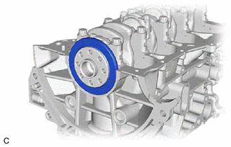
Remove the rear engine oil seal from the cylinder block sub-assembly.
Note
Be careful not to damage the crankshaft.
-
-
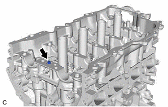
REMOVE CAMSHAFT BEARING CAP SETTING RING PIN
Tech Tips
It is not necessary to remove a camshaft bearing cap setting ring pins unless they are being replaced.
-
*a Camshaft Housing Sub-assembly Top Side Remove the 10 camshaft bearing cap setting ring pins from the camshaft housing sub-assembly.
-