CAMSHAFT REMOVAL
PROCEDURE
-
REMOVE TIMING CHAIN COVER SUB-ASSEMBLY
-
REMOVE NO. 1 CHAIN TENSIONER ASSEMBLY
Tech Tips
-
There are 2 installation types for the No. 1 chain tensioner assembly.
-
Depending on the installation type, the number of bolts, nuts and stud bolts used will vary.
-
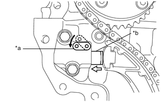
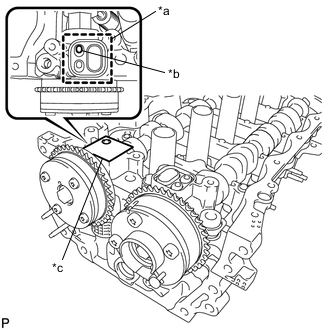
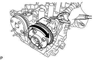
Set the camshaft timing gear assembly, camshaft timing exhaust gear assembly and crankshaft in the positions (20° ATDC) shown in the illustration.
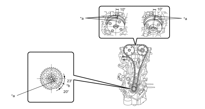
*a Timing Mark *b TDC -
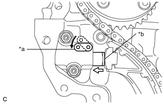
*a Stopper Plate *b Plunger 
Push for No. 1 chain tensioner assembly installed with nut:
-
Push down the stopper plate to release the lock and push in the plunger.
-
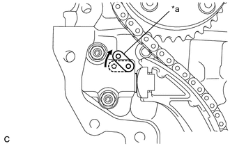
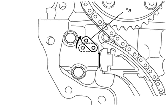
*a Stopper Plate Pull up the stopper plate with the plunger pushed to the end to lock the plunger.
-
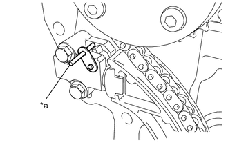
*a Pin Insert a pin of 3 mm (0.118 in.) diameter into the hole in the stopper plate.
-
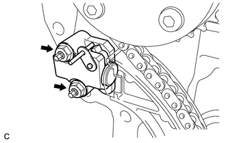
Remove the 2 nuts and No. 1 chain tensioner assembly.
-
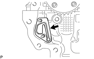
Remove the gasket from the cylinder head sub-assembly.
-
-
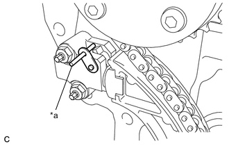
*a Stopper Plate *b Plunger Push for No. 1 chain tensioner assembly installed with bolt:
-
Push down the stopper plate to release the lock and push in the plunger.
-
*a Stopper Plate Pull up the stopper plate with the plunger pushed to the end to lock the plunger.
-
*a Pin Insert a pin of 3 mm (0.118 in.) diameter into the hole in the stopper plate.
-

Remove the 2 bolts, No. 1 chain tensioner assembly and gasket.
-
-
-
REMOVE NO. 2 CHAIN VIBRATION DAMPER
-
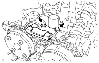
Remove the 2 bolts and No. 2 chain vibration damper.
-
-
REMOVE TIMING CHAIN TENSION ARM
-
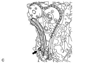
Remove the bolt and timing chain tension arm.
-
-
REMOVE CHAIN SUB-ASSEMBLY
-
Remove the chain sub-assembly.
-
-
REMOVE TIMING CHAIN GUIDE
-
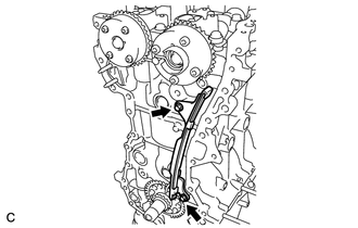
Remove the 2 bolts and timing chain guide.
-
-
INSPECT CAMSHAFT TIMING GEAR ASSEMBLY
-
Check the lock of the camshaft timing gear assembly.
-
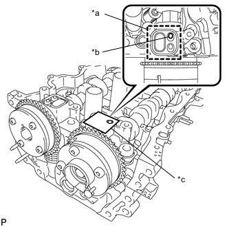
*a Adhesive Tape Sealing Area *b Prick a Hole *c Adhesive Tape Clean the VVT oil hole on the intake side of the camshaft bearing cap, and completely seal the oil hole with adhesive tape or equivalent as shown in the illustration to prevent air from leaking.
Note
Be sure to seal the oil hole completely because air leaks due to insufficient sealing will prevent the lock pin from being released.
-
Prick a hole in the adhesive tape sealing the oil hole as shown in the illustration. (Procedure A)
-
Apply approximately 150 kPa (1.5 kgf/cm2, 22 psi) of air pressure to the hole pricked in procedure A to release the lock pin.
Note
-
If air leaks out, reattach adhesive tape.
-
Cover the oil hole with a piece of cloth when applying air pressure to prevent oil from spraying.
-
-
Forcibly turn the camshaft timing gear assembly in the advance direction (counterclockwise).
Tech Tips
Depending on the air pressure applied, the camshaft timing gear assembly may turn in the advance direction without assistance by hand.
-
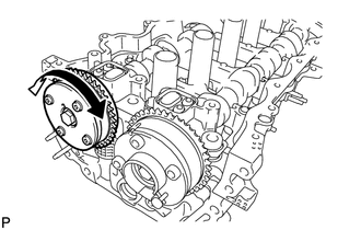
Turn the camshaft timing gear assembly within its movable range (26.5 to 28.5°) 2 or 3 times without turning it to the most retarded position. Make sure that the camshaft timing gear assembly turns smoothly.
-
Remove the adhesive tape from the camshaft bearing cap.
-
-
INSPECT CAMSHAFT TIMING EXHAUST GEAR ASSEMBLY
-
Check the lock of the camshaft timing exhaust gear assembly.
-
*a Adhesive Tape Sealing Area *b Prick a Hole *c Adhesive Tape Clean the VVT oil hole on the exhaust side of the camshaft bearing cap, and completely seal the oil hole with adhesive tape or equivalent as shown in the illustration to prevent air from leaking.
Note
Be sure to seal the oil hole completely because air leaks due to insufficient sealing will prevent the lock pin from being released.
-
Prick a hole in the adhesive tape sealing the oil hole as shown in the illustration. (Procedure B)
-

Apply approximately 200 kPa (2.0 kgf/cm2, 29 psi) of air pressure to the hole pricked in procedure B to release the lock pin.
Note
-
If air leaks out, reattach adhesive tape.
-
Cover the oil hole with a piece of cloth when applying air pressure to prevent oil from spraying.
-
-
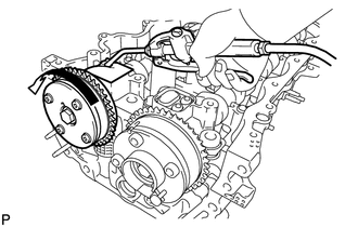
Using a screwdriver with its tip wrapped with tape, forcibly turn the camshaft timing exhaust gear assembly in the retard direction (clockwise).
Note
-
Be sure to keep the camshaft timing exhaust gear assembly in the retard direction using a screwdriver. If the camshaft timing exhaust gear assembly is released, it will return to the most advanced position automatically due to force from the spring.
-
Do not damage the camshaft timing exhaust gear assembly.
-
-
Using a screwdriver with its tip wrapped with tape, turn the camshaft timing exhaust gear assembly within its movable range (19 to 21°) 2 or 3 times without turning it to the most advanced position. Make sure that the camshaft timing exhaust gear assembly turns smoothly.
-
Remove the adhesive tape from the camshaft bearing cap.
-
-
REMOVE CAMSHAFT TIMING EXHAUST GEAR ASSEMBLY
-
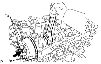
*a Do not Remove *b Hold Remove the bolt while holding the hexagonal portion of the camshaft, then remove the camshaft timing gear assembly.
Note
-
Before removing the camshaft timing gear assembly, make sure that the lock pin has been released.
-
Be sure not to remove the other 4 bolts.
-
Keep the camshaft timing gear assembly horizontal while removing it from the camshaft.
-
-
-
REMOVE CAMSHAFT TIMING GEAR ASSEMBLY
-
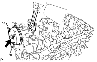
*a Do not Remove *b Hold Remove the bolt while holding the hexagonal portion of the No. 2 camshaft, then remove the camshaft timing exhaust gear assembly.
Note
-
Be sure not to remove the other 4 bolts.
-
Keep the camshaft timing exhaust gear assembly horizontal while removing it from the No. 2 camshaft.
-
-
-
REMOVE CAMSHAFT BEARING CAP
-
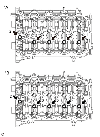
*A Camshaft Bearing Cap Type A *B Camshaft Bearing Cap Type B Uniformly loosen and remove the 5 bolts in the order shown in the illustration.
-
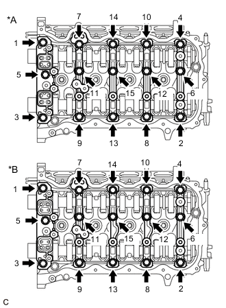
*A Camshaft Bearing Cap Type A *B Camshaft Bearing Cap Type B Uniformly loosen and remove the 15 bolts in the order shown in the illustration.
Note
Uniformly loosen the bolts while keeping the camshaft level.
-
Remove the 5 camshaft bearing caps.
Tech Tips
Arrange the removed parts in the correct order.
-
-
REMOVE NO. 2 CAMSHAFT
-
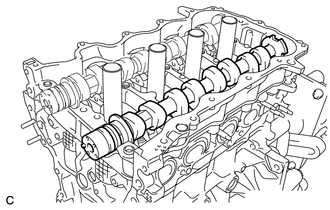
Remove the No. 2 camshaft from the camshaft housing sub-assembly.
-
-
REMOVE CAMSHAFT
-
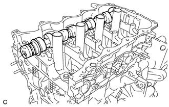
Remove the camshaft from the camshaft housing sub-assembly.
-
-
REMOVE NO. 1 VALVE ROCKER ARM SUB-ASSEMBLY
-
REMOVE VALVE LASH ADJUSTER ASSEMBLY
-
REMOVE CAMSHAFT HOUSING SUB-ASSEMBLY
-

Remove the 3 bolts.
-
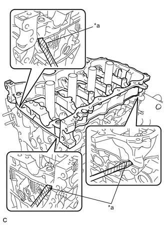
*a Protective Tape Remove the camshaft housing sub-assembly by prying between the cylinder head sub-assembly and camshaft housing sub-assembly with a screwdriver.
Note
Be careful not to damage the contact surfaces of the cylinder head sub-assembly and camshaft housing sub-assembly.
Tech Tips
Tape the screwdriver tip before use.
-
-
INSPECT NO. 1 VALVE ROCKER ARM SUB-ASSEMBLY
-
INSPECT VALVE LASH ADJUSTER ASSEMBLY