ENGINE UNIT(w/o Glow Plug Controller) INSTALLATION

PROCEDURE
-
INSTALL STUD BOLT
-
Using an 8 mm socket wrench, install the 2 stud bolts to the engine mounting bracket RH.
- Torque:
- 10 N*m { 102 kgf*cm, 7 ft.*lbf }
-
-
INSTALL OIL PAN COVER
-
Install the oil pan cover with the 2 bolts and 2 washer plates.
- Torque:
- 7.0 N*m { 71 kgf*cm, 62 in.*lbf }
-
-
INSTALL NO. 2 OIL PAN COVER SILENCER
-
Install the No. 2 oil pan cover silencer with the 2 bolts and 2 washer plates.
- Torque:
- 7.0 N*m { 71 kgf*cm, 62 in.*lbf }
-
-
INSTALL NO. 5 ENGINE COVER
-
Install the No. 5 engine cover with the 2 bolts and 2 washer plates.
- Torque:
- 7.0 N*m { 71 kgf*cm, 62 in.*lbf }
-
-
INSTALL HARNESS BRACKET
-
Install the 2 harness brackets with the 2 bolts.
- Torque:
- 8.0 N*m { 82 kgf*cm, 71 in.*lbf }
-
-
INSTALL V-RIBBED BELT TENSIONER ASSEMBLY
-
Install the V-ribbed belt tensioner assembly with the 2 bolts.
- Torque:
- 24 N*m { 245 kgf*cm, 18 ft.*lbf }
-
-
INSTALL CAMSHAFT POSITION SENSOR
-
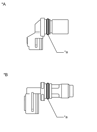
*A w/o Stop And Start System *B w/ Stop And Start System *a O-ring Apply a light coat of engine oil to the O-ring of the camshaft position sensor.
Note
If reusing the camshaft position sensor, be sure to inspect the O-ring.
-
Install the camshaft position sensor with the bolt.
- Torque:
- 7.0 N*m { 71 kgf*cm, 62 in.*lbf }
Note
-
If the camshaft position sensor has been dropped or subjected to a strong impact, replace it.
-
Make sure that the O-ring is not cracked or moved out of place during installation.
-
-
INSTALL HOLE PLUG
-
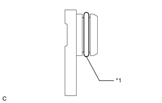
*1 O-ring Apply a light coat of engine oil to the O-ring of the hole plug.
Note
If reusing the hole plug, be sure to inspect the O-ring.
-
Install the hole plug with the bolt.
- Torque:
- 7.0 N*m { 71 kgf*cm, 62 in.*lbf }
Note
Make sure that the O-ring is not cracked or moved out of place during installation.
-
-
INSTALL VACUUM PUMP ASSEMBLY
-
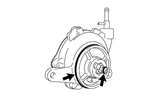

Engine Oil Apply engine oil to 2 new O-rings, and install them to the vacuum pump assembly.
-
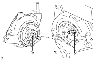
*a Coupling Teeth *b Groove Install the vacuum pump assembly so that the coupling teeth of the vacuum pump assembly and groove of the camshaft can engage.
Note
Ensure that the vacuum pump assembly is installed securely.
-
Install 2 new bolts.
- Torque:
- 21 N*m { 214 kgf*cm, 15 ft.*lbf }
Note
After tightening the bolts, ensure that the contact surface of the vacuum pump assembly is flush with the cylinder head sub-assembly.
-
-
INSTALL INLET WATER PIPE
-
Install the inlet water pipe with the 2 bolts.
- Torque:
- 9.0 N*m { 92 kgf*cm, 80 in.*lbf }
-
-
INSTALL INLET WATER HOSE LH
-
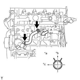
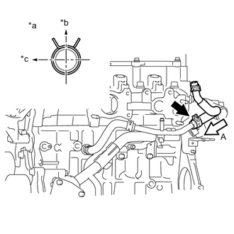
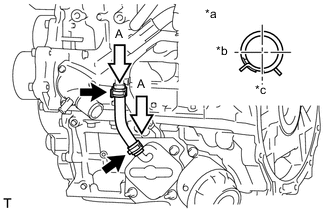
*a View A *b Upper *c LH Install the inlet water hose LH.
Tech Tips
The clip at the inlet water housing can be installed in any orientation, as long as it does not contact any of the surrounding parts.
-
-
INSTALL INLET WATER HOSE RH
-
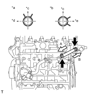
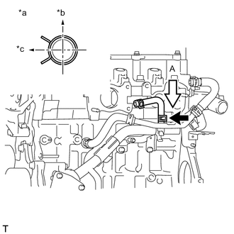
*a View A *b View B *c Upper *d LH *e Rear Install the inlet water hose RH.
-
-
INSTALL WATER BY-PASS PIPE SUB-ASSEMBLY
-
Install a new O-ring to the water by-pass pipe sub-assembly.
Note
Apply water to the O-ring contacting surface of the water inlet housing before installing the water by-pass pipe sub-assembly.
-
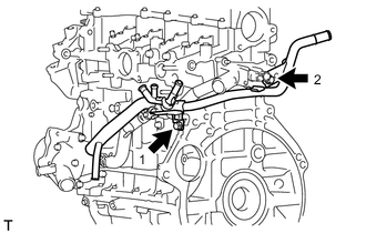
Install the water by-pass pipe sub-assembly with the 2 bolts, in the order shown in the illustration.
- Torque:
- 9.0 N*m { 92 kgf*cm, 80 in.*lbf }
-
Install the 2 hose clamps to the water by-pass pipe sub-assembly.
-
-
INSTALL WATER BY-PASS HOSE
-
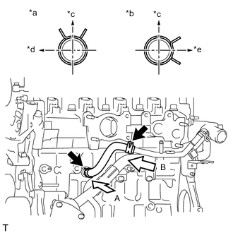
*a View A *b View B *c Upper *d Front *e RH Install the water by-pass hose to the water by-pass pipe sub-assembly.
-
-
INSTALL NO. 2 WATER BY-PASS HOSE
-
*a View A *b Upper *c LH Install the No. 2 water by-pass hose to the water by-pass pipe sub-assembly.
-
-
INSTALL NO. 3 WATER BY-PASS HOSE
-
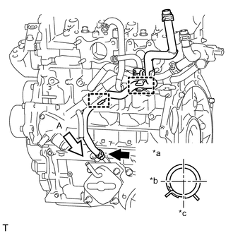
*a View A *b Front *c LH Install the No. 3 water by-pass hose.
-
-
INSTALL NO. 4 WATER BY-PASS HOSE
-
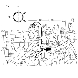
*a View A *b Upper *c Rear Install the No. 4 water by-pass hose to the inlet water pipe.
-
-
INSTALL NO. 2 OIL COOLER HOSE
-
*a View A *b Front *c LH Connect the 2 hose clamps and install the No. 2 oil cooler hose.
Note
Align the paint mark of the No. 2 oil cooler hose with the center of the clamp.
-
Install the 2 hose clamps.
Note
Align the paint mark of the No. 2 oil cooler hose with the center of the clamp.
-
-
INSTALL OIL COOLER HOSE
-
*a View A *b Front *c LH Install the oil cooler hose.
-
-
INSTALL NO. 2 CYLINDER HEAD COVER
-
Install the No. 2 cylinder head cover.
-
-
INSTALL NO. 1 INTAKE MANIFOLD INSULATOR
-
Install the No. 1 intake manifold insulator.
-
-
INSTALL COMMON RAIL ASSEMBLY
-
Install the common rail assembly to the cylinder head sub-assembly with the 2 bolts.
- Torque:
- 21 N*m { 214 kgf*cm, 15 ft.*lbf }
-
-
INSTALL NO. 1 SUPPLY PUMP DRIVE COUPLING
-
TEMPORARILY INSTALL SUPPLY PUMP ASSEMBLY
Note
Clean the seal surfaces of the inlet fuel pipe sub-assembly, supply pump assembly and common rail assembly before installation.
-
Apply a light coat of engine oil to a new O-ring.
-
Install the O-ring to the supply pump assembly.
-
Temporarily install the supply pump assembly with the 3 bolts.
-
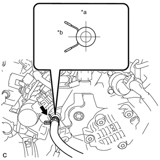
*a Upper *b LH Connect the No. 1 fuel hose to the supply pump assembly.
-
-
INSTALL FUEL INLET PIPE SUB-ASSEMBLY
Note
-
When replacing the supply pump assembly, the fuel inlet pipe sub-assembly must also be replaced.
-
Replace the fuel inlet pipe sub-assembly with a new one when the fuel inlet pipe sub-assembly has been removed and reinstalled more than 5 times.
-
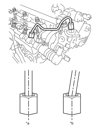
*a CORRECT *b INCORRECT Temporarily install the fuel inlet pipe sub-assembly to the supply pump assembly and common rail assembly.
Note
Install the fuel inlet pipe sub-assembly and union nut with their centers aligned.
-
Install the supply pump assembly with the 3 bolts.
- Torque:
- 21 N*m { 214 kgf*cm, 15 ft.*lbf }
-
Using a 17 mm union nut wrench, tighten the fuel inlet pipe sub-assembly union nut on the common rail assembly side.
- Torque:
- 28 N*m { 286 kgf*cm, 21 ft.*lbf }
Note
Use the formula to calculate special torque values for situations where a union nut wrench is combined with a torque wrench Click here.
-
Using a 17 mm wrench, hold the supply pump assembly nut, and using a 17 mm union nut wrench, tighten the fuel inlet pipe sub-assembly union nut on the supply pump assembly side.
- Torque:
- 28 N*m { 286 kgf*cm, 21 ft.*lbf }
Note
Use the formula to calculate special torque values for situations where a union nut wrench is combined with a torque wrench Click here.
-
-
INSTALL NO. 2 FUEL HOSE
-
Install the No. 2 fuel hose.
-
-
INSTALL INJECTION NOZZLE SEAT
-
INSTALL INJECTOR ASSEMBLY
-
INSTALL NOZZLE HOLDER CLAMP SEAT
-
INSTALL NO. 1 NOZZLE HOLDER CLAMP
-
INSTALL NOZZLE LEAKAGE PIPE ASSEMBLY
-
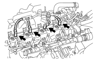
Install the nozzle leakage pipe assembly to each injector assembly.
-
Make sure that the lock bush is at the top position.
-
Connect the rest arm to the injector assembly and push both sides of the return plug until the rest arm engages the injector assembly, as shown in the illustration.
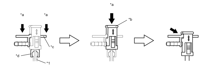
*1 Injector - - *a Push *b Lock Bush *c Return Plug *d Rest Arm Tech Tips
Push the nozzle leakage pipe assembly until it makes a click sound.
-
Push the lock bush until it fits with the return plug, as shown in the illustration.
-
-
Connect the nozzle leakage pipe assembly and install a new retainer spring to the supply pump assembly.
-
-
INSTALL NOZZLE LEAKAGE PIPE SET CLAMP
-
Install the 3 nozzle leakage pipe set clamps to the nozzle leakage pipe assembly.
-
-
INSTALL NO. 2 INTAKE MANIFOLD INSULATOR
-
INSTALL GLOW PLUG ASSEMBLY
-
Clean the cylinder head sub-assembly glow plug assembly installation holes.
-
Install the 4 glow plug assemblies.
- Torque:
- 12.5 N*m { 127 kgf*cm, 9 ft.*lbf }
-
-
INSTALL NO. 1 GLOW PLUG CONNECTOR
-
Install the No. 1 glow plug connector with the 4 nuts.
- Torque:
- 2.2 N*m { 22 kgf*cm, 19 in.*lbf }
-
Install the 4 screw grommets.
-
-
INSTALL NO. 1 INJECTION PIPE SUB-ASSEMBLY
-
INSTALL NO. 2 INJECTION PIPE SUB-ASSEMBLY
-
INSTALL NO. 3 INJECTION PIPE SUB-ASSEMBLY
-
INSTALL INTAKE AIR CONNECTOR WITH DIESEL THROTTLE BODY
-
Install a new intake air connector gasket to the cylinder head sub-assembly.
-
Install the intake air connector with diesel throttle body with the 2 bolts and 2 nuts.
- Torque:
- 23 N*m { 235 kgf*cm, 17 ft.*lbf }
-
Connect the vacuum transmitting hose to the hose clamp.
-
-
INSTALL ENGINE OIL LEVEL DIPSTICK GUIDE
-
Install a new O-ring to the engine oil level dipstick guide.
-
Install the engine oil level dipstick guide with the bolt.
- Torque:
- 9.0 N*m { 92 kgf*cm, 80 in.*lbf }
-
-
INSTALL ENGINE OIL LEVEL DIPSTICK
-
Install the engine oil level dipstick.
-
-
INSTALL EGR VALVE (ELECTRIC EGR CONTROL VALVE ASSEMBLY)
-
INSTALL HARNESS BRACKET
-
INSTALL NO. 1 EGR COOLER BRACKET
-
Install the No. 1 EGR cooler bracket to the cylinder head sub-assembly with the 2 bolts.
- Torque:
- 23 N*m { 235 kgf*cm, 17 ft.*lbf }
-
-
INSTALL EGR WITH COOLER PIPE ASSEMBLY
-
Install 2 new gaskets to the cylinder head sub-assembly and electric EGR control valve assembly.
-
Install the EGR with cooler pipe assembly with the 4 bolts and 2 nuts.
- Torque:
- 23 N*m { 235 kgf*cm, 17 ft.*lbf }
-
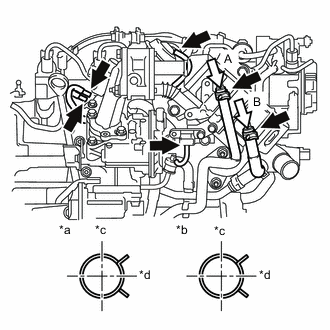
*a View A *b View B *c Rear *d LH Connect the No. 2 water by-pass hose to the EGR with cooler pipe assembly.
-
Connect the No. 2 oil cooler hose to the EGR with cooler pipe assembly.
-
Connect the vacuum hose to the EGR with cooler pipe assembly.
-
Connect the 3 vacuum transmitting hoses to the vacuum switching valve assembly and turbo pressure sensor.
-
-
INSTALL GENERATOR BRACKET
-
Install the generator bracket to the cylinder block sub-assembly with the 2 bolts.
- Torque:
- 40 N*m { 408 kgf*cm, 30 ft.*lbf }
-
-
INSTALL GENERATOR ASSEMBLY
-
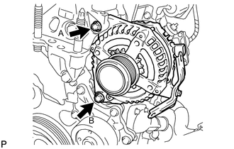
Install the generator assembly with the 2 bolts.
- Torque:
- Bolt A
- 35 N*m { 357 kgf*cm, 26 ft.*lbf }
- Bolt B
- 54 N*m { 551 kgf*cm, 40 ft.*lbf }
-
-
INSTALL ENGINE COVER BRACKET (w/ No. 1 Engine Cover)
-
Install the engine cover bracket to the engine mounting bracket RH with the bolt.
- Torque:
- 21 N*m { 214 kgf*cm, 15 ft.*lbf }
-