ENGINE UNIT(w/ Glow Plug Controller) INSPECTION

PROCEDURE
-
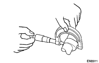
INSPECT OIL CHECK VALVE SUB-ASSEMBLY
-
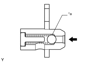
*a Ball 
Push Push the ball of the oil check valve sub-assembly to check if it is stuck.
Note
If the oil check valve sub-assembly is stuck, replace the oil check valve sub-assembly.
-
-
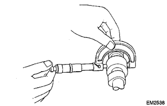
INSPECT NO. 1 VALVE ROCKER ARM SUB-ASSEMBLY
-
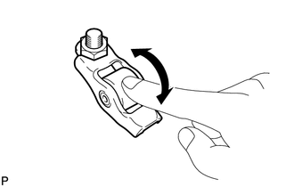
Turn the roller by hand to check that it turns smoothly.
If the roller does not turn smoothly, replace the No. 1 valve rocker arm sub-assembly.
-
-
INSPECT CHAIN SUB-ASSEMBLY
-
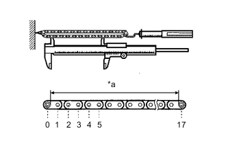
*a Measurement Area Using a spring scale, apply 140 N (14 kgf, 31.5 lbf) to the chain sub-assembly then measure its length.
Maximum Chain Sub-assembly Length 156.5 mm (6.16 in.) Tech Tips
Measure the length in at least 3 places and calculate the average length.
If the length is greater than the maximum, replace the chain sub-assembly.
-
-
INSPECT NO. 2 CHAIN SUB-ASSEMBLY
-
*a Measurement Area Using a spring scale, apply 140 N (14 kgf, 31.5 lbf) to the No. 2 chain sub-assembly then measure its length.
Maximum No. 2 Chain Sub-assembly Length 115.2 mm (4.54 in.) Tech Tips
Measure the length in at least 3 places and calculate the average length.
If the length is greater than the maximum, replace the No. 2 chain sub-assembly.
-
-
INSPECT NO. 1 CHAIN TENSIONER ASSEMBLY
-
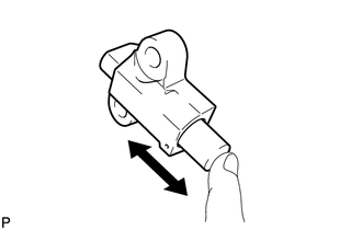
Check that the plunger moves smoothly when the cam is raised with your finger.
-
Release the ratchet pawl and check that the plunger does not move when pushed with your finger. If necessary, replace the No. 1 chain tensioner assembly.
-
-
INSPECT CAMSHAFT TIMING SPROCKET
-
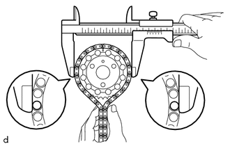
Place the chain sub-assembly around the camshaft timing sprocket.
-
Using a vernier caliper, measure the diameter of the camshaft timing sprocket including the chain sub-assembly.
Minimum Camshaft Timing Sprocket Diameter (w/ chain sub-assembly) 134.8 mm (5.31 in.) Note
The vernier caliper must be in contact with the chain sub-assembly rollers when measuring.
If the diameter is less than the minimum, replace the camshaft timing sprocket.
-
-
INSPECT CRANKSHAFT TIMING SPROCKET
-
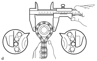
Place the chain sub-assembly around the crankshaft timing sprocket.
-
Using a vernier caliper, measure the diameter of the crankshaft timing sprocket including the chain sub-assembly.
Minimum Crankshaft Timing Sprocket Diameter (w/ chain sub-assembly) 71.51 mm (2.82 in.) Note
The vernier caliper must be in contact with the chain sub-assembly rollers when measuring.
If the diameter is less than the minimum, replace the crankshaft timing sprocket.
-
-
INSPECT OIL PUMP DRIVE GEAR
-
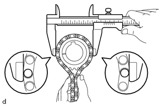
Place the No. 2 chain sub-assembly around the oil pump drive gear.
-
Using a vernier caliper, measure the diameter of the oil pump drive gear including the No. 2 chain sub-assembly.
Minimum Oil Pump Drive Gear Diameter (w/ No. 2 chain sub-assembly) 56.4 mm (2.22 in.) Note
The vernier caliper must be in contact with the No. 2 chain sub-assembly rollers when measuring.
If the diameter is less than the minimum, replace the oil pump drive gear.
-
-
INSPECT OIL PUMP DRIVE SHAFT GEAR
-
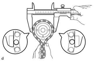
Place the No. 2 chain sub-assembly around the oil pump drive shaft gear.
-
Using a vernier caliper, measure the diameter of the oil pump drive shaft gear including the No. 2 chain sub-assembly.
Minimum Oil Pump Drive Shaft Gear Diameter (w/ No. 2 chain sub-assembly) 58.6 mm (2.31 in.) Note
The vernier caliper must be in contact with the No. 2 chain sub-assembly rollers when measuring.
If the diameter is less than the minimum, replace the oil pump drive shaft gear.
-
-
INSPECT CHAIN TENSIONER SLIPPER
-
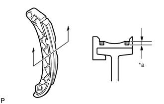
*a Wear Using a vernier caliper, measure the wear of the chain tensioner slipper.
Maximum Wear 1.0 mm (0.0394 in.) If the wear is greater than the maximum, replace the chain tensioner slipper.
-
-
INSPECT NO. 1 CHAIN VIBRATION DAMPER
-
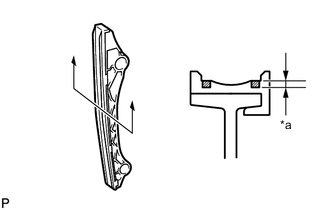
*a Wear Using a vernier caliper, measure the wear of the No. 1 chain vibration damper.
Maximum Wear 1.0 mm (0.0394 in.) If the wear is greater than the maximum, replace the No. 1 chain vibration damper.
-
-
INSPECT CHAIN TENSIONER PLATE
-
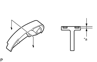
*a Wear Using a vernier caliper, measure the wear of the chain tensioner plate.
Maximum Wear 1.0 mm (0.0394 in.) If the wear is greater than the maximum, replace the chain tensioner plate.
-
-
INSPECT CAMSHAFT
-
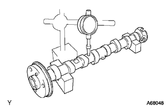
Inspect the runout.
-
Place the camshaft on V-blocks.
-
Using a dial indicator, measure the runout of the camshaft at the center journal.
Maximum Runout 0.03 mm (0.00118 in.) If the runout is greater than the maximum, replace the camshaft.
-
-
Inspect the height of the cam lobes.
-
Using a micrometer, measure the cam lobe height.
Standard Cam Lobe Height for Intake: 34.484 to 34.584 mm (1.3576 to 1.3616 in.) for Exhaust: 35.299 to 35.399 mm (1.3897 to 1.3937 in.) Minimum Cam Lobe Height for Intake: 34.434 mm (1.3557 in.) for Exhaust: 35.249 mm (1.3878 in.) If the cam lobe height is less than the minimum, replace the camshaft.
-
-
Inspect the diameter of the cam journals.
-
Using a micrometer, measure the cam journal diameter.
Standard Cam Journal Diameter 23.979 to 23.995 mm (0.9441 to 0.9447 in.) If the cam journal diameter is not as specified, check the oil clearance.
-
-
-
INSPECT CYLINDER HEAD SET BOLT
-
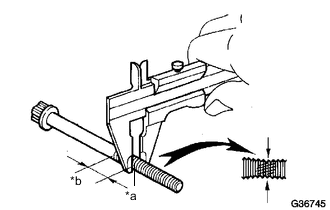
*a Measuring Point *b 55 mm (2.165 in.) Using a vernier caliper, measure the minimum outer diameter of the bolt at the measuring point.
Standard Diameter 11.5 to 12.0 mm (0.453 to 0.472 in.) Minimum Diameter 11.2 mm (0.441 in.) If the outer diameter is less than the minimum, replace the cylinder head set bolt.
-