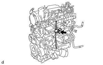
ENGINE UNIT(w/ Glow Plug Controller) REMOVAL

PROCEDURE
-
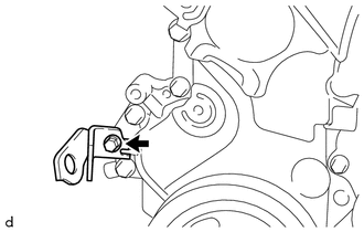
REMOVE ENGINE COVER BRACKET
-
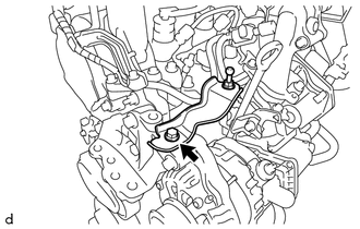
Remove the bolt and engine cover bracket from the engine mounting bracket RH.
-
-
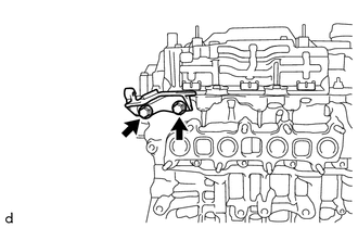
REMOVE GENERATOR ASSEMBLY
-
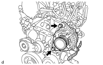
Remove the 2 bolts and generator assembly from the engine mounting bracket RH and generator bracket.
-
-
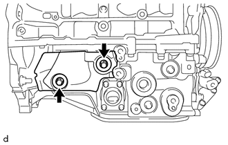
REMOVE GENERATOR BRACKET
-
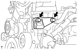
Remove the 2 bolts and generator bracket from the cylinder block sub-assembly.
-
-
REMOVE EGR WITH COOLER PIPE ASSEMBLY
-
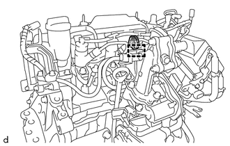
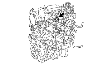
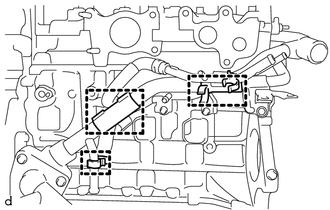
Disengage the clamp to separate the connector from the EGR with cooler pipe assembly.
-
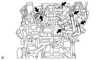
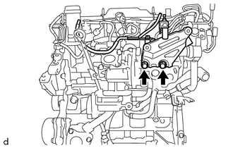
Disconnect the 3 vacuum transmitting hoses from the EGR with cooler pipe assembly.
-
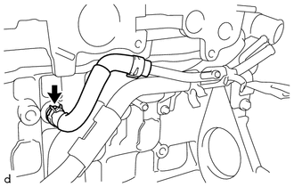
Disconnect the vacuum hose from the EGR with cooler pipe assembly.
-
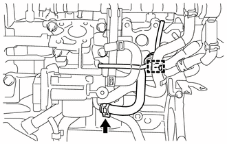
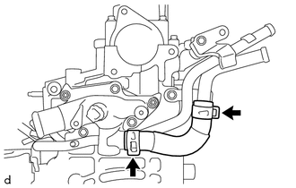
Slide the hose clip and disconnect the No. 2 oil cooler hose from the EGR with cooler pipe assembly.
-
Slide the hose clip and disconnect the No. 2 water by-pass hose from the EGR with cooler pipe assembly.
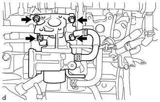
-
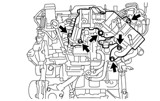
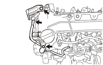
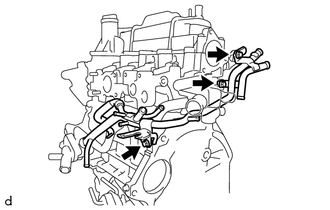
Remove the 5 bolts, nut and EGR with cooler pipe assembly from the EGR valve (electric EGR control valve assembly), No. 1 EGR cooler bracket and cylinder head sub-assembly.
-
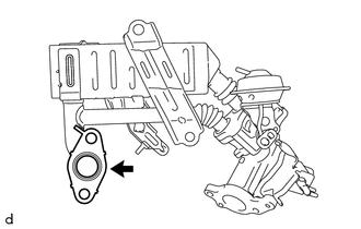
Remove the EGR pipe gasket from the EGR with cooler pipe assembly.
-
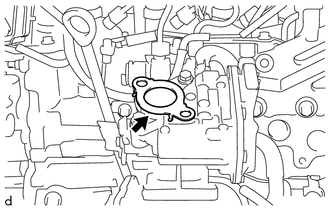
Remove the EGR inlet gasket from the EGR valve (electric EGR control valve assembly).
-
-
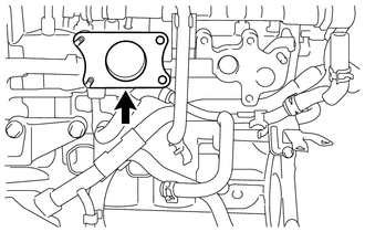
REMOVE NO. 1 EGR COOLER BRACKET
-
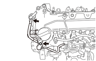
Remove the 2 bolts and No. 1 EGR cooler bracket from the cylinder head sub-assembly.
-
-
REMOVE HARNESS BRACKET (for LHD)
-
Disconnect the vacuum hose from the vacuum pump assembly.
-
Remove the 2 bolts and 2 harness brackets from the cylinder head cover sub-assembly.
-
-
REMOVE HARNESS BRACKET (for RHD)
-
Disconnect the vacuum hose from the vacuum pump assembly.
-
Remove the bolt and harness bracket from the cylinder head cover sub-assembly.
-
-
REMOVE EGR VALVE (ELECTRIC EGR CONTROL VALVE ASSEMBLY)
-
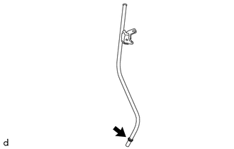
REMOVE ENGINE OIL LEVEL DIPSTICK
-
Remove the engine oil level dipstick from the engine oil level dipstick guide.
-
-
REMOVE ENGINE OIL LEVEL DIPSTICK GUIDE
-
Remove the bolt and engine oil level dipstick guide from the intake air connector and oil pan sub-assembly.
-
Remove the O-ring from the engine oil level dipstick guide.
-
-
REMOVE INTAKE AIR CONNECTOR WITH DIESEL THROTTLE BODY
-
Disengage the clamp to separate the vacuum transmitting hose assembly from the No. 2 oil cooler hose.
-
Slide the hose clip and disconnect the No. 3 water by-pass hose from the intake air connector with diesel throttle body.
-
Remove the 2 bolts, 2 nuts and intake air connector with diesel throttle body from the cylinder head sub-assembly.
-
Remove the intake air connector gasket from the cylinder head sub-assembly.
-
-
REMOVE NOZZLE LEAKAGE PIPE ASSEMBLY
-
REMOVE NO. 1 INJECTION PIPE SUB-ASSEMBLY
-
REMOVE NO. 2 INJECTION PIPE SUB-ASSEMBLY
-
REMOVE NO. 3 INJECTION PIPE SUB-ASSEMBLY
-
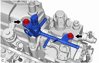
REMOVE FUEL INLET PIPE SUB-ASSEMBLY
-
Remove the bolt and No. 2 injection pipe clamp from the fuel inlet pipe sub-assembly and No. 4 injection pipe sub-assembly.
-
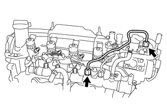
Using a 17 mm union nut wrench, loosen the 2 union nuts, and remove the fuel inlet pipe sub-assembly from the supply pump assembly and common rail assembly.
Note
To prevent contamination by foreign matter, after removing the fuel inlet pipe sub-assembly, protect the connecting portions of the supply pump assembly and common rail assembly with plastic bags.
-
-
REMOVE NO. 4 INJECTION PIPE SUB-ASSEMBLY
-
REMOVE NO. 2 FUEL HOSE
-
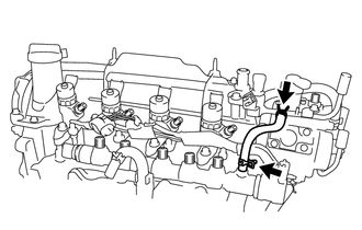
Slide the 2 hose clips and remove the No. 2 fuel hose from the No. 2 nozzle leakage pipe and common rail assembly.
-
-
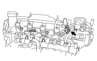
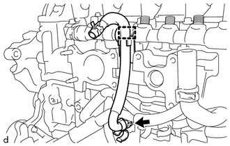
REMOVE NO. 1 FUEL HOSE
-
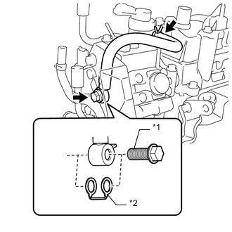
*1 Union Bolt *2 Gasket Slide the hose clip and disconnect the No. 1 fuel hose from the No. 2 nozzle leakage pipe.
-
Remove the union bolt and No. 1 fuel hose and gasket from the supply pump assembly.
-
-
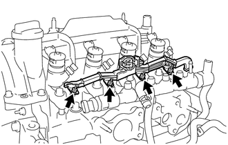
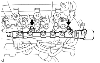
REMOVE NO. 2 NOZZLE LEAKAGE PIPE
-
Remove the 2 bolts and No. 2 nozzle leakage pipe from the fuel pump protector and cylinder head cover sub-assembly.
-
-
REMOVE FUEL PUMP PROTECTOR
-
REMOVE SUPPLY PUMP ASSEMBLY
-
REMOVE NO. 1 GLOW PLUG CONNECTOR
-
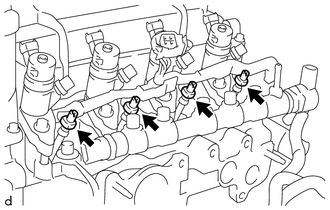
Remove the 4 glow plug screw grommets.
-
Remove the 4 nuts and No. 1 glow plug connector from each glow plug assembly.
-
-
REMOVE GLOW PLUG ASSEMBLY
-
REMOVE COMMON RAIL ASSEMBLY
-
Disengage the clamp to separate the No. 4 water by-pass hose from the common rail assembly.
-
Slide the hose clip and remove the No. 4 water by-pass hose from the water inlet pipe.
-
Remove the 2 bolts and common rail assembly from the cylinder head sub-assembly.
-
-
REMOVE NO. 1 NOZZLE HOLDER CLAMP
-
REMOVE NOZZLE HOLDER CLAMP SEAT
-
REMOVE INJECTOR ASSEMBLY
-
REMOVE INJECTION NOZZLE SEAT
-
REMOVE OIL COOLER HOSE
-
Slide the 2 hose clips and remove the oil cooler hose from the water by-pass pipe sub-assembly and oil cooler assembly.
-
-
REMOVE NO. 2 OIL COOLER HOSE
-
Disengage the 4 hose clamps to separate the No. 2 oil cooler hose from the 2 clamps and water by-pass pipe sub-assembly.
-
Slide the hose clip and remove the No. 2 oil cooler hose from the oil filter bracket sub-assembly.
-
-
REMOVE NO. 3 WATER BY-PASS HOSE
-
Slide the hose clip and remove the No. 3 water by-pass hose from the water by-pass pipe sub-assembly.
-
-
REMOVE NO. 2 WATER BY-PASS HOSE
-
Slide the hose clip and remove the No. 2 water by-pass hose from the water by-pass pipe sub-assembly.
-
-
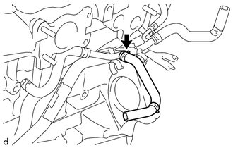
REMOVE NO. 1 TURBO WATER HOSE
-
Slide the hose clip and remove the No. 1 turbo water hose from the water by-pass pipe sub-assembly.
-
-
REMOVE NO. 2 TURBO WATER HOSE
-
Slide the hose clip and remove the No. 2 turbo water hose from the water by-pass pipe sub-assembly.
-
-
REMOVE NO. 6 WATER BY-PASS HOSE
-
Slide the 2 hose clips and remove the No. 6 water by-pass hose from the water by-pass pipe sub-assembly and water outlet sub-assembly.
-
-
DISCONNECT WATER BY-PASS HOSE
-
Slide the hose clip and disconnect the water by-pass hose from the tube connector.
-
-
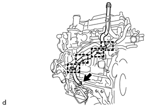
REMOVE WATER BY-PASS PIPE SUB-ASSEMBLY
-
Remove the 3 clamps from the water by-pass pipe sub-assembly.
-
Remove the 3 bolts and water by-pass pipe sub-assembly from the No. 2 turbocharger stay, cylinder head sub-assembly, cylinder block sub-assembly and water inlet housing.
-
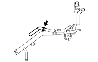
Slide the hose clip and remove the water by-pass hose from the water by-pass pipe sub-assembly.
-
Remove the O-ring from the water by-pass pipe sub-assembly.
-
-
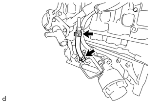
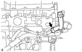
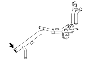
REMOVE WATER INLET HOSE RH
-
Slide the 2 hose clips and remove the water inlet hose RH from the water outlet sub-assembly and water inlet pipe.
-
-
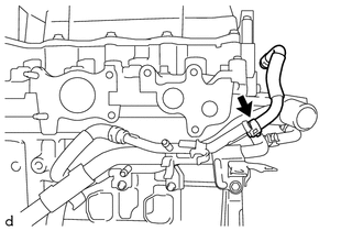
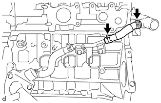
REMOVE WATER INLET HOSE LH
-
Slide the 2 hose clips and remove the water inlet hose LH from the water inlet pipe and water inlet housing.
-
-
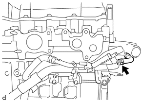
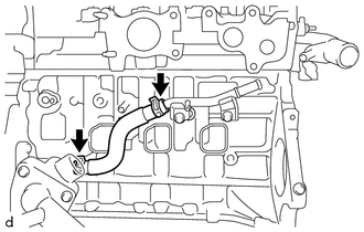
REMOVE WATER INLET PIPE
-
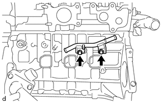
Remove the 2 bolts and water inlet pipe from the cylinder block sub-assembly.
-
-
REMOVE VACUUM PUMP ASSEMBLY
-
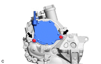
Remove the 2 bolts and vacuum pump assembly from the cylinder head sub-assembly.
-
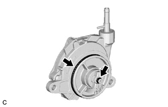
Remove the 2 O-rings from the vacuum pump assembly.
-
-
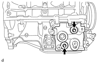
REMOVE V-RIBBED BELT TENSIONER ASSEMBLY
-
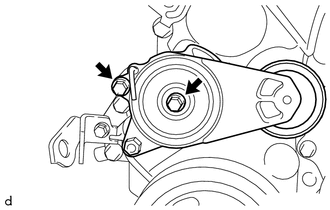
Remove the 2 bolts and V-ribbed belt tensioner assembly from the timing chain cover sub-assembly.
-
-
REMOVE HARNESS BRACKET
-
Remove the bolt and harness bracket from the timing chain cover sub-assembly.
-
-
REMOVE NO. 2 TURBOCHARGER STAY
-
Remove the 2 bolts and No. 2 turbocharger stay from the cylinder head sub-assembly.
-
-
REMOVE OIL PAN COVER
-
Remove the 2 bolts, 2 plate washers and oil pan cover from the oil pan sub-assembly.
-
-
REMOVE NO. 2 OIL PAN COVER SILENCER
-
Remove the 2 bolts, 2 plate washers and No. 2 oil pan cover silencer from the oil pan sub-assembly.
-