FRONT CRANKSHAFT OIL SEAL(w/o Glow Plug Controller) INSTALLATION

PROCEDURE
-
INSTALL TIMING CHAIN COVER OIL SEAL
-
Apply MP grease to a new timing chain cover oil seal lip.
Note
Keep the lip free from foreign matter.
-
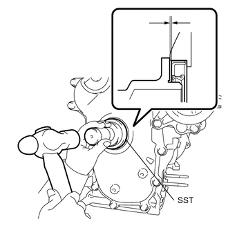
Using SST and a hammer, tap in the new timing chain cover oil seal until its surface is flush with the timing chain cover sub-assembly.
- SST
- 09223-22010
Oil Seal Tap in Depth -0.6 to 0 mm (-0.0236 to 0 in.) Note
-
Do not tap in the timing chain cover oil seal at an angle.
-
Wipe off excess grease from the crankshaft.
-
-
INSTALL CRANKSHAFT DAMPER SUB-ASSEMBLY
-
Align the key with the key groove of the crankshaft damper sub-assembly, and install the crankshaft damper sub-assembly to the crankshaft.
-
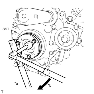
*a Hold *b Turn Using SST, hold the crankshaft damper sub-assembly.
- SST
- 09213-58014
- 09330-00021
-
Tighten the bolt to the specified torque.
- Torque:
- 210 N*m { 2141 kgf*cm, 155 ft.*lbf }
-
-
INSTALL ENGINE MOUNTING INSULATOR SUB-ASSEMBLY RH
-
Set the engine mounting insulator RH sub-assembly onto the vehicle and engine mouthing bracket RH.
-
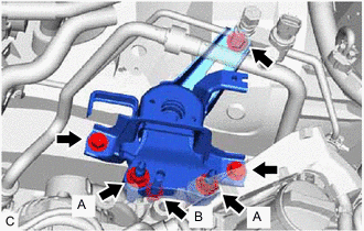
Install the engine mounting insulator sub-assembly RH with the 3 bolts and 3 nuts.
- Torque:
- Bolt
- 95 N*m { 969 kgf*cm, 70 ft.*lbf }
- Nut (A)
- 95 N*m { 969 kgf*cm, 70 ft.*lbf }
- Nut (B)
- 52 N*m { 530 kgf*cm, 38 ft.*lbf }
-
Connect the cooler pipe clamp to the engine mounting insulator sub-assembly RH.
-
Install the cooler pipe clamp bracket with the bolt.
- Torque:
- 9.8 N*m { 100 kgf*cm, 87 in.*lbf }
-
-
INSTALL RADIATOR RESERVE TANK ASSEMBLY
-
Install the radiator reserve tank assembly with the 2 bolts.
- Torque:
- 5.0 N*m { 51 kgf*cm, 44 in.*lbf }
-
-
INSTALL FRONT EXHAUST PIPE ASSEMBLY
-
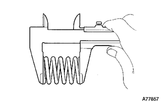
Using a vernier caliper, measure the free length of the compression springs.
Minimum 41.5 mm (1.63 in.) If the free length is less than the minimum, replace the compression spring.
-
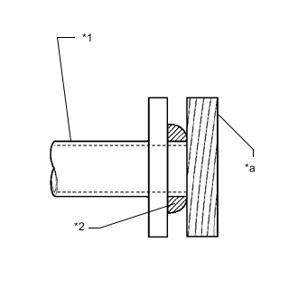
*1 No. 2 Exhaust Manifold Converter Sub-assembly *2 Gasket *a Wooden Block Using a plastic hammer and wooden block, tap in a new gasket until its surface is flush with the No. 2 exhaust manifold converter sub-assembly.
Note
-
Be careful with the installation direction of the gasket.
-
Do not reuse the gasket.
-
Do not damage the gasket.
-
Do not push in the gaskets by using the front exhaust pipe sub-assembly when connecting it.
-
-
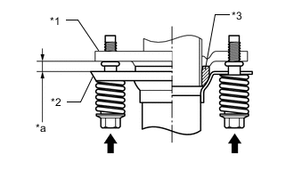
*1 No. 2 Exhaust Manifold Converter Sub-assembly *2 Front Exhaust Pipe Assembly *3 Gasket *a Space Between Flanges: 8.5 mm (0.335 in.) Install the front exhaust pipe assembly to the No. 2 exhaust manifold converter sub-assembly with the 2 bolts and 2 compression springs.
- Torque:
- 43 N*m { 438 kgf*cm, 32 ft.*lbf }
Tech Tips
After installation, check that the space between the flanges of the No. 2 exhaust manifold converter sub-assembly and front exhaust pipe assembly are consistent front-to-rear and left-to-right.
-
-
INSTALL FRONT ENGINE MOUNTING BRACKET LOWER REINFORCEMENT (w/ Reinforcement)
-
INSTALL FRONT SUSPENSION MEMBER REINFORCEMENT RH
-
INSTALL V-RIBBED BELT
-
INSPECT FOR OIL LEAK
-
INSTALL NO. 1 ENGINE COVER (w/ No. 1 Engine Cover)
-
INSTALL REAR ENGINE UNDER COVER RH
-
INSTALL NO. 1 ENGINE UNDER COVER (for Half Cover Type)
-
INSTALL NO. 1 ENGINE UNDER COVER (for Full Cover Type)
-
INSTALL FRONT WHEEL RH
- Torque:
- 103 N*m { 1050 kgf*cm, 76 ft.*lbf }