CYLINDER HEAD GASKET(w/ Glow Plug Controller) INSTALLATION
PROCEDURE
-
INSTALL CYLINDER HEAD GASKET
-
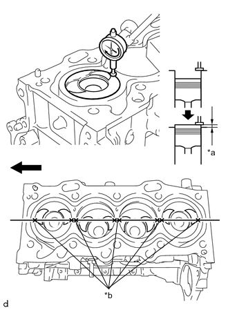
*a Protrusion *b Measurement Points 
Front of Engine Inspect the protrusion height of the piston heads.
-
Place a dial indicator on the cylinder block sub-assembly as shown in the illustration.
Note
Make sure that the dial indicator is at a right angle to the cylinder block sub-assembly top surface.
-
Measure the protrusion height of the piston head of each cylinder at 2 points as shown in the illustration.
-
-
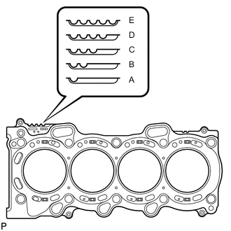
Select a new cylinder head gasket.
-
Select the highest protrusion height among the 8 measurements recorded. It will be used to select a new cylinder head gasket.
Piston Protrusion Piston Protrusion
mm (in.)
Number of Gasket Cutouts Gasket Size 0.525 to 0.575
(0.0207 to 0.0226)
1 (A) 0.576 to 0.625
(0.0227 to 0.0246)
2 (B) 0.626 to 0.675
(0.02465 to 0.02657)
3 (C) 0.676 to 0.725
(0.0266 to 0.0285)
4 (D) 0.726 to 0.775
(0.0286 to 0.0305)
5 (E)
-
-
Install the cylinder head gasket.
-
Apply seal packing (diameter 3.5 to 4.5 mm (0.138 to 0.177 in.)) to the cylinder block sub-assembly as shown in the illustration.
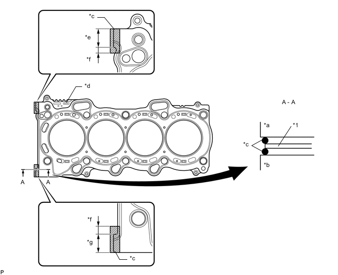
*1 Cylinder Head Gasket - - *a Cylinder Head Side *b Cylinder Block Side *c Seal Packing *d Lot No. *e 18.0 mm (0.709 in.) *f 1.0 to 6.0 mm (0.0394 to 0.236 in.) *g 18.5 mm (0.728 in.) - - Seal Packing Toyota Genuine Seal Packing Black, Three Bond 1207B or equivalent Note
Remove any oil from the contact surface.
-
Place a new cylinder head gasket on the cylinder block sub-assembly with the Lot No. stamp facing upward.
-
Apply seal packing (Diameter 3.5 to 4.5 mm (0.138 to 0.177 in.)) to the top surface of the cylinder head sub-assembly again as shown in the illustration.
Seal Packing Toyota Genuine Seal Packing Black, Three Bond 1207B or equivalent Note
-
Remove any oil from the contact surface.
-
Install the cylinder head sub-assembly within 3 minutes, and tighten the bolts within 15 minutes of applying the seal packing.
-
Do not start the engine for at least 2 hours after installing the cylinder head gasket.
-
-
-
-
INSTALL CYLINDER HEAD SUB-ASSEMBLY
-
CONNECT WATER INLET HOSE RH
-
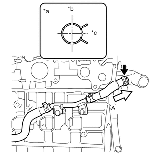
*a View (A) *b Upper of Engine *c Rear of Engine Connect the water inlet hose RH to the water outlet sub-assembly and slide the hose clip to secure it.
Note
Perform the installation with the hose clip at the correct angle.
-
-
INSTALL NO. 1 VALVE ROCKER ARM SUB-ASSEMBLY
-
INSTALL CAMSHAFT
-
INSTALL CHAIN SUB-ASSEMBLY
-
INSTALL NO. 1 CHAIN VIBRATION DAMPER
-
INSTALL CHAIN TENSIONER SLIPPER
-
INSTALL NO. 1 CHAIN TENSIONER ASSEMBLY
-
INSTALL TIMING CHAIN COVER OIL SEAL
-
INSTALL TIMING CHAIN COVER SUB-ASSEMBLY
-
CONNECT WATER INLET HOSE LH
-
INSTALL CRANKSHAFT DAMPER SUB-ASSEMBLY
-
INSTALL CAMSHAFT POSITION SENSOR
-
INSTALL NO. 2 TIMING CHAIN COVER
-
INSTALL ENGINE MOUNTING BRACKET RH
-
CHECK VALVE CLEARANCE
-
ADJUST VALVE CLEARANCE
-
INSTALL CYLINDER HEAD COVER SUB-ASSEMBLY
-
INSTALL V-RIBBED BELT TENSIONER ASSEMBLY
-
INSTALL VACUUM PUMP ASSEMBLY
-
INSTALL WATER BY-PASS PIPE SUB-ASSEMBLY
-
INSTALL NO. 2 OIL COOLER HOSE
-
INSTALL INJECTION NOZZLE SEAT
-
INSTALL INJECTOR ASSEMBLY
-
INSTALL NOZZLE HOLDER CLAMP SEAT
-
INSTALL NO. 1 NOZZLE HOLDER CLAMP
-
INSTALL COMMON RAIL ASSEMBLY
-
INSTALL GLOW PLUG ASSEMBLY
-
INSTALL NO. 1 GLOW PLUG CONNECTOR
-
INSTALL SUPPLY PUMP ASSEMBLY
-
INSTALL FUEL PUMP PROTECTOR
-
INSTALL NO. 2 NOZZLE LEAKAGE PIPE
-
CONNECT NO. 2 FUEL HOSE
-
CONNECT NO. 1 FUEL HOSE
-
INSTALL NO. 4 INJECTION PIPE SUB-ASSEMBLY
-
INSTALL FUEL INLET PIPE SUB-ASSEMBLY
-
INSTALL NO. 3 INJECTION PIPE SUB-ASSEMBLY
-
INSTALL NO. 2 INJECTION PIPE SUB-ASSEMBLY
-
INSTALL NO. 1 INJECTION PIPE SUB-ASSEMBLY
-
INSTALL NOZZLE LEAKAGE PIPE ASSEMBLY
-
INSTALL INTAKE AIR CONNECTOR WITH DIESEL THROTTLE BODY
-
INSTALL ENGINE OIL LEVEL DIPSTICK GUIDE
-
INSTALL ENGINE OIL LEVEL DIPSTICK
-
INSTALL EGR VALVE (ELECTRIC EGR CONTROL VALVE ASSEMBLY)
-
INSTALL HARNESS BRACKET (for LHD)
-
INSTALL HARNESS BRACKET (for RHD)
-
INSTALL NO. 1 EGR COOLER BRACKET
-
INSTALL EGR WITH COOLER PIPE ASSEMBLY
-
INSTALL GENERATOR BRACKET
-
INSTALL GENERATOR ASSEMBLY
-
INSTALL ENGINE COVER BRACKET
-
REMOVE ENGINE FROM ENGINE STAND